Precise nozzle temperature control in plastic injection molding requires translating the physical thermal mass of your tooling into a precise electrical specification. An accurate hot runner heater power sizing process bridges the gap between calculating the raw energy required to heat the steel and determining if that energy can be safely concentrated into the available physical space without causing thermal degradation.
At Hongtai heater factory, our thermal engineering team resolves erratic hot runner heater heat-up time and premature element failure by strictly analyzing both total wattage and surface load. By applying a structured hot runner coil heater power calculation followed by a precise hot runner coil heater watt density calculation, mold designers can specify heating elements that ensure stable melt flow and extend service life.
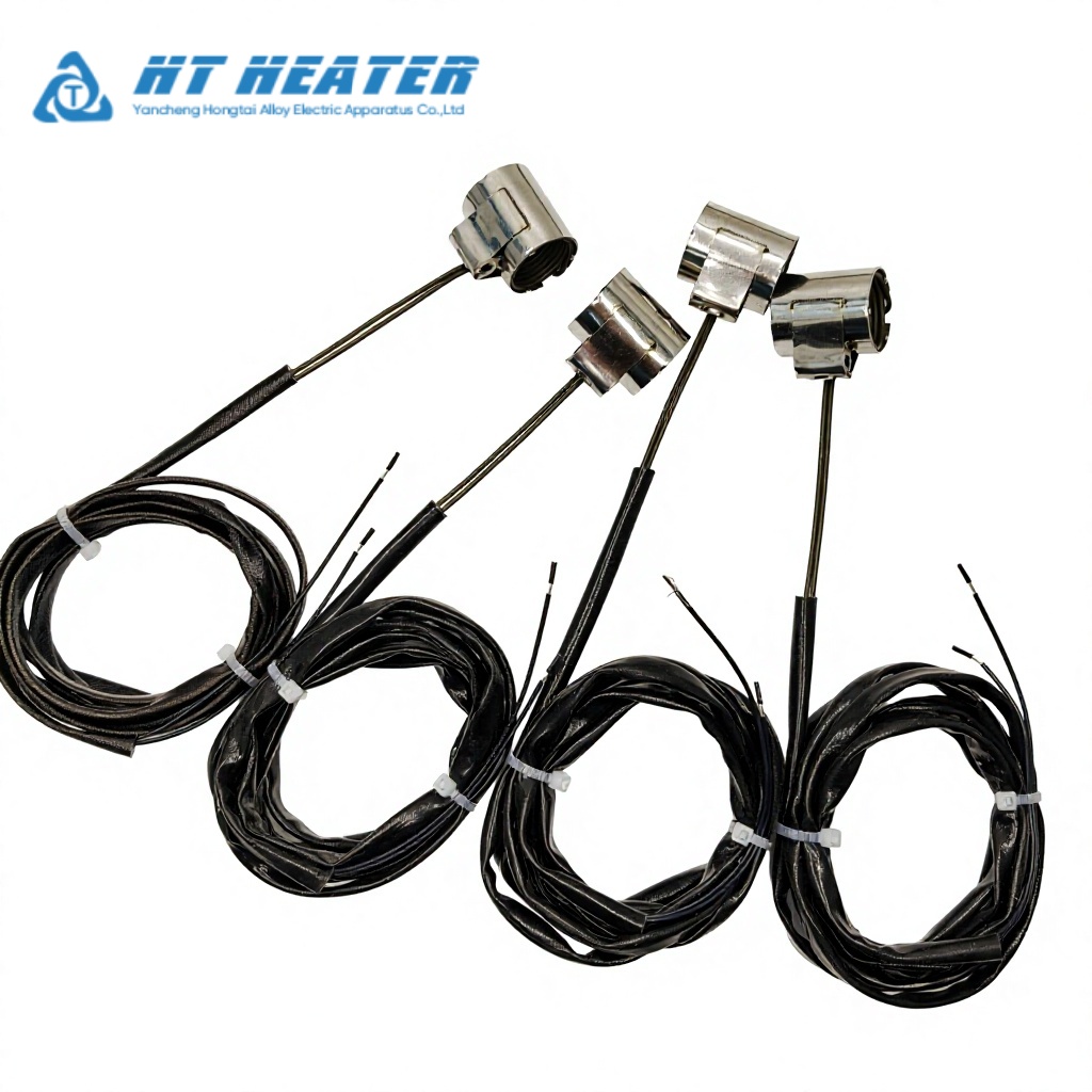
1.The Coil Heater Power Sizing Formula
Before evaluating the watt density, engineers must calculate the baseline electrical power (Watts) required to bring the steel nozzle to the operating temperature within the target timeframe.
The fundamental thermal calculation for sensible heat is:
P = (m · c · ΔT) / (t · η)
Variable Breakdown:
P (Power): Total required wattage (W).
m (Mass): The weight of the steel nozzle being heated (kg).
c (Specific Heat Capacity): The thermal capacity of mold steel, typically 460 J/(kg·°C) for standard tool steels.
ΔT (Temperature Rise): The difference between the starting ambient temperature and the target melt temperature (°C).
t (Heat-up Time): The hot runner heater heat-up time target (seconds).
η (Thermal Design Factor / Heat-Loss Allowance): A decimal value representing thermal efficiency. Hot runner systems suffer massive conduction losses to the cold mold plates. An assumed allowance (e.g., 0.5) is often used as a starting point to ensure adequate baseline power.
2. Example: Baseline Hot Runner Heater Wattage Calculation
Let’s apply the coil heater power sizing formula to a standard nozzle to establish a baseline.
Nozzle Mass: 0.8 kg
Target Temperature Rise: 20 °C to 220 °C (ΔT = 200 °C)
Target Heat-up Time: 10 minutes (600 seconds)
Thermal Design Factor Assumption: 0.5
P = (0.8 · 460 · 200) / (600 · 0.5)
Total Energy Required (Sensible Heat): 0.8 × 460 × 200 = 73,600 Joules
Power Before Losses: 73,600 / 600 = 122.6 Watts
Total Calculated Power: 122.6 / 0.5 = 245.2 Watts (Typically rounded to a standard 250W).
Understanding the Calculation’s Limitations
It is critical for engineers to understand that specifying a 250W heater does not strictly guarantee the nozzle will reach 220°C in exactly 10 minutes under production conditions. This foundational hot runner heater wattage calculation primarily accounts for the sensible heat of the isolated nozzle. It does not fully calculate the dynamic thermal losses occurring through the manifold interfaces, radiation to surrounding cavity plates, the heat capacity of the flowing plastic melt, or continuous dynamic heat-sinking during rapid injection cycles.
3. The Hot Runner Coil Heater Watt Density Calculation
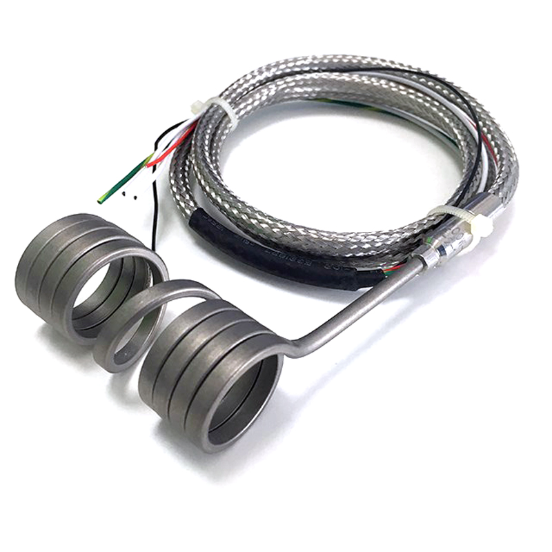
Once the required total power (e.g., 250W) is established, you must determine if this wattage can be safely applied to the nozzle without causing localized overheating, insulation degradation, or premature element failure. This is achieved through the hot runner coil heater watt density calculation.
Watt density (Surface Load W/cm²) is the total wattage divided by the active heated surface area of the coil.
Formula:
Watt Density (W/cm²) = Total Power (W) / Active Surface Area (cm²)
Calculating Active Surface Area:
You must calculate the surface area based on the heater’s cross-sectional profile and its active hot runner heater heated length (strictly excluding the unheated cold zones at the lead exits).
- Determine Perimeter: Calculate the perimeter of the coil’s cross-section. For example, a 3.3 × 3.3 mm square profile has a perimeter of 13.2 mm (1.32 cm).
- Determine Heated Length: Use the uncoiled, flat active length (e.g., 50 cm).
- Calculate Area: Active Area = 1.32 cm × 50 cm = 66 cm2
Final Watt Density Calculation:
- 250W / 66 cm2 = 3.78 W/cm2
4. Why Safe Watt Density Limits are Application-Dependent
Unlike immersion fluid heaters, there is no universal “safe limit” for hot runner nozzle heater watt density. Acceptable surface loads are highly dynamic and depend entirely on how efficiently the generated heat can be transferred away from the heater sheath and into the nozzle steel.
If the calculated watt density is exceptionally high, the internal core temperature of the heater will spike. This does not merely “melt the resistance wire”; it primarily causes excessive sheath temperatures, rapid internal dielectric (MgO) insulation degradation, localized overheating, and eventual electrical leakage. To understand the root causes of these issues, review our guide on Troubleshooting Hot Runner Coil Heater Failures: Element Burnout and Current Leakage.
The allowable watt density for any given design relies on these specific engineering variables:
- Installation Fit (Negative Tolerance): A tight “hot grip” drastically improves heat transfer, allowing the heater to safely sustain higher watt densities. A loose fit traps heat, leading to premature failure. For calculation methods on proper interference fits, see Hongtai HT-CR Coil Heater ID Tolerance: Ensuring Perfect Nozzle Fit Without Thermal Lag.
- Nozzle Material Thermal Conductivity: Highly conductive materials (like beryllium copper alloys) strip heat away from the coil much faster than standard H13 tool steel, safely accommodating higher localized power.
- Heater Construction & Profile: Different cross-sections provide different contact areas. If the watt density is too high for a round profile, engineers often switch to flat-sided profiles to increase surface contact. Review Hot Runner Coil Heater Cross Section: Round vs. Square vs. Rectangular for geometrical comparisons.
- Advanced Heat Transfer Matrices: For extreme high-power applications in compact spaces, standard coil heaters may be replaced entirely with advanced composite systems. Read about Hongtai Pressed-In Brass Hot Runner Heater Design: Eliminate Air Gaps & Thermal Lag in Hot Runners.
Moving from Power Calculation to Custom Specification
The hot runner coil heater power calculation and subsequent watt density check confirm the thermodynamic feasibility of your design. The final step is translating these mathematical requirements into physical OEM specifications, including exact lead lengths, built-in thermocouple configurations, and precise cold zones. For a complete breakdown of this final engineering step, refer to our Hot Runner Coil Heater Engineering Guide: Selection, Fit & Systemic Troubleshooting.
Do you want to determine the most reliable watt density for your application?
Frequent heater failures due to excessive sheath temperatures, localized overheating, or internal insulation degradation cause unacceptable downtime in high-volume injection molding.
Hongtai heater factory custom-engineers every heating element by thoroughly evaluating your specific nozzle mass, mold geometry, and required heat-up times to determine the most reliable watt density for your application.
Company: Hongtai heater factory
Technical Sales Consultation: Contact Hongtai Engineering Team
Contact Us Hot Runner Experts: www.hongtai-heater.com
B2B Related Technical Resources
- Nozzle Fit & Tolerance: Hongtai HT-CR Coil Heater ID Tolerance: Ensuring Perfect Nozzle Fit Without Thermal Lag
- Thermal Profile Design: Distributed Wattage Coil Heater: Optimizing Hot Runner Temperature Profiles
- Air-Gap Elimination: Hongtai Pressed-In Brass Hot Runner Heater Design: Eliminate Air Gaps & Thermal Lag in Hot Runners
- Sensor & Feedback Integration: Coil Heater with Built-in Thermocouple: Type J vs. K and Lead Exit Engineering
- Sheath Metallurgy Selection: Sheath Materials for Hot Runner Coil Heaters: Stainless Steel vs. Nickel
- Cross-Section Geometry: Hot Runner Coil Heater Cross Section: Round vs. Square vs. Rectangular
- Lead Wire & Terminal Protection: Coil Heater Lead Wires: Selection, Temperature Ratings, and Protection Options
- Installation Standard SOP: How to Install Hot Runner Coil Heaters: Mounting SOP & Preventing Heater Deformation
- Energy Efficiency Upgrades: Insulated Coil Heater Guide for Hot Runners
- Field Failure Diagnostics: Troubleshooting Hot Runner Coil Heater Failures: Element Burnout and Current Leakage