How to install hot runner coil heaters correctly is a critical procedure for mold toolmakers, maintenance technicians, and field engineers aiming to eliminate premature element burnout and thermal lag. Improper assembly techniques—such as forced mechanical stretching, aggressive hammering, or improper clamping—distort precision coil geometry, fracture compacted Magnesium Oxide (MgO) insulation, and leave air gaps that cause rapid localized overheating.
At Hongtai Industry Heater, our engineering team has developed this Standard Operating Procedure (SOP) to establish correct cold-assembly guidelines, preheat fastening routines, and anti-deformation protocols for injection molding lines.
1. Common Installation Errors & Failure Mechanisms
Field failures are frequently traced back to mechanical abuse during initial mold tool assembly rather than manufacturing defects. Mold technicians must eliminate four destructive installation practices:
| Improper Installation Practice | Internal Failure Mechanism | Final Failure Mode |
|---|---|---|
| Violent Hammering | Cracks Internal MgO Powder | Dielectric Arc & Dead Short |
| Forced Stretching | Distorts Pitch Geometry | Uneven Thermal Hot Spots |
| Sharp Lead Bending | Shears Weld Junction | Open Circuit Failure |
| Loose ID Tolerance | Air Gap Thermal Barrier | Dry Burning Element Melt-Off |
Forced Coil Stretching and Pitch Distortion
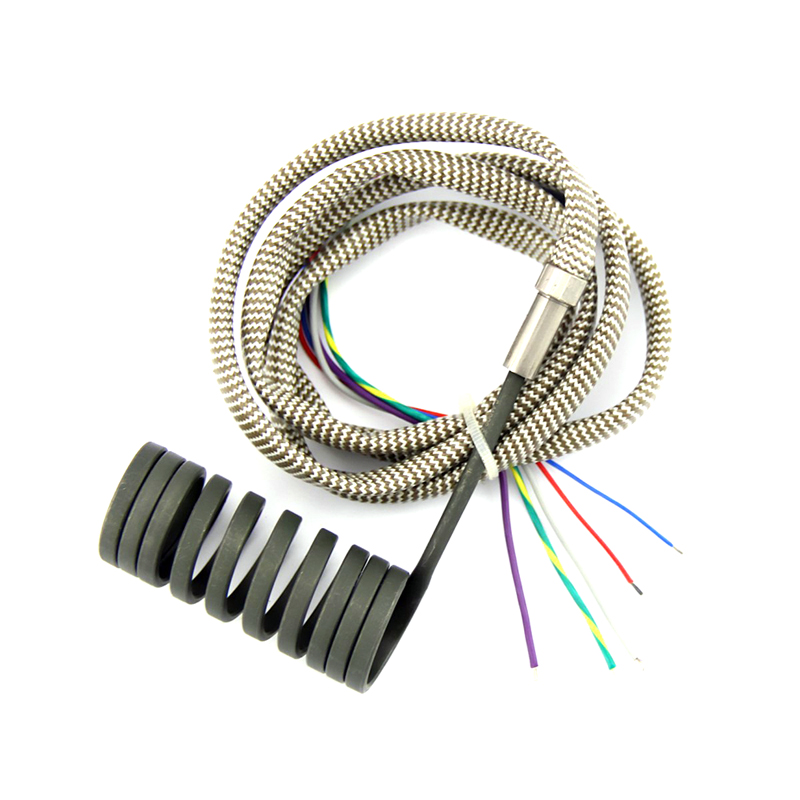
Attempting to manually pull or stretch a coil heater to cover a longer nozzle body alters the designed pitch distribution. In engineered heating elements, such as distributed wattage coil heaters, coil spacing is specifically wound tighter at the nozzle ends to offset heat sink dissipation. Stretching disrupts this balance, creating localized hot spots (> 1000°C) that destroy internal resistance wire.
Impact Shock and Sheath Deformation
Striking a coil heater with a metal or hard plastic hammer to force it onto an oversized nozzle sheath crushes the outer wall. This compresses the internal MgO layer below its required dielectric thickness, leading to immediate ground faults or insulation breakdown upon startup.
Transition Header Strain
Bending transition leads sharply at the ceramic exit collar puts stress on the internal junction where cold nickel leads connect to the heating wire. Always refer to coil heater lead wire selection and protection guidelines to preserve strain-relief structures.
2. Pre-Installation Inspection & Tool Checklist
Before mounting any heater onto a hot runner nozzle, execute this standard pre-installation verification:
- Dimensional Verification: Measure the nozzle outer diameter (OD) and heater inner diameter (ID) using precision calipers to ensure compliance with HT-CR coil heater ID tolerance standards.
- Electrical Testing:
- Resistance Check: Measure cold resistance across power terminals using a multimeter. Ensure value meets target specifications based on R = V2 / P (±5% to 10%).
- Insulation Test: Test dielectric resistance with a 500V DC Megohmmeter from power leads to the outer sheath. Cold insulation must exceed 500 MΩ
- Cross-Section Geometry Check: Confirm whether the nozzle cavity requires flat, square, or round profiles by checking hot runner coil heater cross section profiles.
- Nozzle Surface Preparation: Clean all anti-seize residue, carbonized plastic, or burrs from the nozzle surface using fine emery cloth and degreaser.
3. Standard Operating Procedure (SOP) for Coil Heater Mounting
Follow this 4-step SOP during mold assembly to guarantee 360° thermal contact and prevent mechanical expansion deformation:
| Installation Step | Standard Operating Procedure (SOP) | Key Prevention Feature |
|---|---|---|
| Step 1: Cold Alignment | Slide heater smoothly onto the nozzle. Strictly avoid twisting or hammering. | Prevents internal MgO powder cracking. |
| Step 2: Lock Sleeve Fit | Secure brass or steel lock sleeve tightly for full 360° concentric contact. | Elimates air gap thermal barriers. |
| Step 3: Lead Routing | Maintain a minimum 10mm straight lead exit before applying any bending radius. | Prevents sheared weld junctions and opens. |
| Step 4: Soft-Start Bake | Heat to 100°C gradually to vent internal moisture and settle the thermal fit. | Avoids moisture-induced short circuits. |
Step 1: Cold Alignment and Push-Fit Mounting
- Align the heater parallel to the nozzle axis.
- Gently push the heater onto the nozzle body using even hand pressure on the rear ceramic header.
- NEVER twist the coil against its winding direction, as this expands the ID permanently and reduces surface contact.
- If binding occurs, stop immediately. Check nozzle OD tolerances rather than forcing the unit.
Step 2: Lock Sleeve Attachment & Clamping
- Slide a precision brass or stainless steel clamping sleeve over the coil assembly.
- For optimal heat transfer, consider using an integrated Hongtai pressed-in brass hot runner heater design which encapsulates the coil inside brass to permanently eliminate air gaps.
- Torque clamping screws evenly in a cross-pattern to prevent asymmetric crushing.
Step 3: Lead Wire Routing and Stress Relief
- Ensure lead wires exit the mold channel with a minimum straight length of 10mm from the transition joint before introducing bends.
- Maintain a bend radius at least 3X the outer diameter of the lead wire/armor.
- Secure wires inside mold wireways using heat-resistant hold-down plates to prevent pinching during mold plate assembly.
Step 4: Controlled Soft-Start Preheat & Tightening Routine
- Connect the heater to the temperature control system.
- Set PID controller output to 20%–30% duty cycle (or 80V–100V output).
- Preheat the nozzle assembly to 100°C–120°C for 15–20 minutes. This vents ambient moisture absorbed by hygroscopic MgO insulation and allows thermal expansion of the nozzle to lock the heater in place naturally.
- Retighten lock sleeve screws while warm to compensate for initial thermal seating.
- If GFCI breakers trip or electrical errors display during startup, consult troubleshooting hot runner coil heater failures.
4. Featured Hot Runner Coil Heating Components
Hongtai provides specialized hot runner heating units engineered with reinforced transition headers and precise ID tolerances:
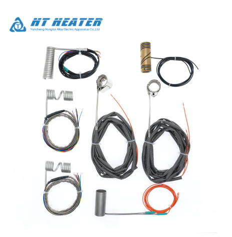
- 6mm Hot Runner Coil Heater for Injection Nozzle: Precision-wound element built for tight nozzle cavities, offering uniform heat delivery and high resistance to thermal deformation.
- 220V Brass Sleeve Hot Runner Coil Heater: Premium encapsulated assembly featuring a brass outer sleeve that eliminates air gaps and protects internal coils from mechanical damage.
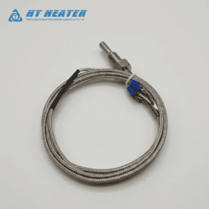
- 300W Coil Heater with Built-in Thermocouple: Features integrated Type J or Type K thermocouples for real-time tip feedback, supporting precise PID temperature regulation.
Contact Hongtai for Technical Support & Custom Heating Assemblies
Hongtai Industry Heater engineers design custom hot runner coil heaters, brass sleeve assemblies, and heavy-duty lead options specifically engineered for high-stress injection molding machinery. Featuring precision-wound 80/20 NiCr resistance elements, compacted high-purity MgO insulation, and strict inner diameter (ID) tolerances, our thermal assemblies withstand severe thermal cycling, resist mechanical deformation during mounting, and eliminate air gaps on complex nozzle bodies. By adhering to our standardized installation SOP and soft-start preheat protocols, field technicians can resolve frequent element burnout challenges, delivering uniform heat distribution, exceptional vibration resistance, and reliable long-term performance across demanding processing environments.
Need technical assistance with mold installation or custom heater sizing?
Hongtai Industry Heater supplies robust hot runner coil heaters, brass sleeve assemblies, and flexible lead options to injection molding plants worldwide.
B2B Related Technical Resources
- Nozzle Fit & Tolerance: Hongtai HT-CR Coil Heater ID Tolerance: Ensuring Perfect Nozzle Fit Without Thermal Lag
- Thermal Profile Design: Distributed Wattage Coil Heater: Optimizing Hot Runner Temperature Profiles
- Air-Gap Elimination: Hongtai Pressed-In Brass Hot Runner Heater Design: Eliminate Air Gaps & Thermal Lag in Hot Runners
- Sensor & Feedback Integration: Coil Heater with Built-in Thermocouple: Type J vs. K and Lead Exit Engineering
- Sheath Metallurgy Selection: Sheath Materials for Hot Runner Coil Heaters: Stainless Steel vs. Nickel
- Lead Wire & Terminal Protection: Coil Heater Lead Wires: Selection, Temperature Ratings, and Protection Options
- Field Failure Diagnostics: Troubleshooting Hot Runner Coil Heater Failures: Element Burnout and Current Leakage