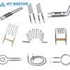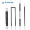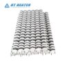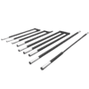
Silicon carbide heating elements (commonly referred to as SiC heating rods or glow bars) serve as the primary radiant heat source for high-temperature industrial furnaces, ceramic sintering kilns, magnetic material pusher kilns, and non-ferrous metal melting furnaces operating between 1000°C and 1550°C. However, field engineers frequently encounter premature rod breakage, arcing at metallized terminal ends, or rapid power decay within months of commissioning. In most cases, these failures stem not from material defects, but from dimensional mismatches, excessive surface loading, or inadequate voltage reserve during the initial SiC element selection phase.
For high-temperature furnace design engineers and ceramic kiln manufacturers, effective specification goes far beyond picking a geometric profile—it requires systematically matching chamber geometry, atmosphere chemistry, surface watt density, and electrical aging behavior (if you are still comparing metallic resistance wire, SiC, and MoSi₂ technologies across temperature ranges and atmospheres, see our foundational guide: Industrial Furnace Heating Elements: NiCr vs. SiC vs. MoSi₂). This engineering guide provides a practical step-by-step methodology for specifying the right SiC furnace heater.
1. Silicon Carbide Heating Element Selection: Key Engineering Inputs
Before locking in a part number, engineers must translate furnace operating conditions into five sequential selection inputs:
- Chamber Operating Temperature & Atmosphere Composition: Define both continuous operating temperature and maximum boost temperature, as well as whether the chamber contains clean oxidizing air, nitrogen, reducing protective gas, water vapor, or alkaline ceramic volatiles (used to determine maximum allowable surface watt density in W/cm²).
- Mounting Space & Termination Layout: Determine whether elements will mount horizontally or vertically, and whether dual-side through-wall access or single-side blind termination is required (used to screen SiC heating element shapes).
- Internal Chamber Span & Refractory Wall Thickness: Measure the effective internal chamber width/height and total insulation thickness (used to define Hot Zone length HZ, Cold End length CZ, and Overall Length OL).
- Zone Power Demand & Element Quantity: Divide total zone thermal load by the allowable surface loading to calculate the total required radiating surface area, which establishes element outer diameter (OD) and element count.
- Supply Voltage, Circuit Topology & Calibrated Resistance: Align available transformer voltage taps (or SCR power controller output range) with series/parallel wiring layouts to specify the nominal calibrated resistance (Ω) per element.
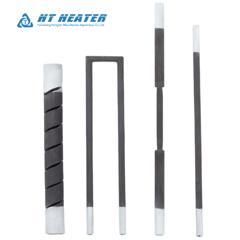
2. Silicon Carbide Heater Types and Shapes (ED, DB, U, W, SG/SGR)
Industrial silicon carbide heater types are manufactured primarily via reaction-bonded or recrystallized sintering processes. Different SiC heating element shapes dictate refractory drilling diameters, cold-end parasitic heat loss, and radiant flux distribution:
| Element Type & Common Code | Geometric Profile | Termination Location | Mounting Orientation | Engineering Advantages & Typical Furnace Applications |
| ED Type (Straight Rod) | Uniform diameter rod (hot zone and cold ends share the same OD) | Dual-ended (passes through opposite walls) | Horizontal / Vertical | Uniform through-hole sizing and simplest installation/extraction; widely used in roller hearths, tunnel kilns, and box furnaces |
| DB Type (Dumbbell) | Dumbbell straight rod (slender hot zone with thickened cold ends) | Dual-ended (requires stepped or larger wall bores) | Horizontal / Vertical | Enlarged cold-end cross-section lowers terminal resistance and reduces parasitic wall heating; ideal for thick-walled, energy-efficient sintering kilns |
| U Type (U-Shape) | Two straight heating legs bridged by a high-density SiC crossbeam | Single-ended (2 terminals on one side) | Vertical hanging / Horizontal | Requires wall penetrations and wiring on only one side of the furnace; ideal for furnaces placed against walls, top-fired annealing furnaces, and glass forehearths |
| W Type (Three-Leg / M-Type) | Three heating legs joined by bottom crossbeam bridges | Single-ended (3 terminals on one side) | Vertical hanging / Horizontal | Designed for wide-span radiant coverage (such as float glass tin bath roofs); exact 3-phase Star/Delta or single-phase wiring must follow the element’s internal bridge schematic |
| SG / SGR Type (Spiral Grooved) | Tubular SiC body machined with a single (SG) or double reverse (SGR) helix | Dual-ended (SG) / Single-ended (SGR) | Vertical / Horizontal | Helical current path significantly increases resistance per unit length; ideal for compact tube furnaces, crucible furnaces, and blind radiant tubes |
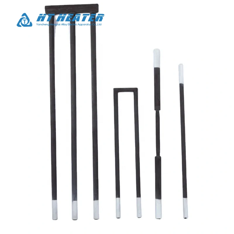
Engineering Procurement Note: Model abbreviations for spiral-grooved elements (such as SG, SGR, or SCR) and multi-leg profiles vary across manufacturers. Never order replacement elements based solely on a letter code. Always specify single-ended vs. dual-ended termination, helix configuration, and exact segment dimensions on your drawing. Furthermore, if your radiant tube application operates below 1050°C and requires ductile metallic wire supported by refractory segments rather than rigid ceramic rods, compare your design against Ceramic Bobbin Heaters: Construction, Resistance Wire & Applications.
3. How to Specify Hot Zone (HZ), Cold Ends (CZ), and Overall Length (OL)
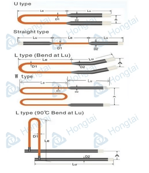
Every silicon carbide heating element consists of three functional axial zones: a high-resistance central Hot Zone (HZ), low-resistance Cold Ends (CZ) that pass through the refractory insulation, and Metallized Aluminum Terminals at the outer tips.
3.1 Three Dimensional Sizing Rules (Preliminary Design Reference)
- Hot Zone Length (HZ): The HZ must reside entirely within the open furnace chamber. Critical Rule: Never allow the Hot Zone to extend inside the refractory brick bore or ceramic fiber wall! If the heating section enters the insulated wall passage, trapped heat causes localized temperature runaway, melting the hot-to-cold weld joint and damaging surrounding refractory bricks. As a preliminary design reference, engineers typically specify HZ equal to or slightly shorter than the internal chamber span (e.g., recessed 10 mm – 25 mm per side, depending on wall bevel geometry).
- Cold End Length (CZ): Each cold end length equals the refractory wall thickness plus an external terminal extension outside the furnace shell (typically 50 mm – 100 mm as a preliminary reference to keep aluminum terminal clamps ventilated and away from shell heat).
- Element-to-Element Center Spacing: To prevent mutual radiative shielding and overheating between adjacent rods, center-to-center spacing is generally designed at no less than 2× to 3× the element outer diameter (OD), adjusted for workload geometry and thermal uniformity targets.
3.2 Practical Sizing Example: Box Sintering Furnace ED-Type SiC Calculation
Suppose an OEM is designing a box sintering furnace operating continuously at a 1300°C chamber temperature in clean air. The internal chamber width is W = 500 mm, each side wall insulation thickness is 200 mm, and the required zone heating power is 18 kW using horizontally mounted ED-type straight rods:
- Step 1 (Define HZ, CZ, and OL): Allowing a 10 mm clearance inset from each inner wall prevents hot-zone wall overheating, yielding HZ = 500 – (2 × 10) = 480 mm (or standard 450 mm / 500 mm stock sizes). Each cold end is sized at CZ = 200 mm (wall) + 75 mm (external extension) = 275 mm. Total length OL = 480 + (2 × 275) = 1030 mm.
- Step 2 (Calculate Diameter OD & Quantity): For recrystallized SiC in a 1300°C air chamber, preliminary reference surface loading typically falls between 5 and 7 W/cm²; selecting a conservative 5.5 W/cm² and testing an outer diameter of OD = 25 mm (2.5 cm) gives a radiating surface area per rod of Ah = π × 2.5 × 48 cm ≈ 377 cm². Allowable power per rod is Psingle = 377 × 5.5 ≈ 2073 W ≈ 2.0 kW. Meeting the 18 kW zone load requires 9 elements (arranged in 3 balanced three-phase circuits of 3 elements each) of size ∅25 × 480 × 275 mm.
- Step 3 (Verify Voltage & Resistance Matching): With 9 elements wired as 3 parallel branches of 3 elements in series (2000 W per element) and a nominal calibrated hot resistance of R = 2.0 Ω, the required initial voltage per rod is Vsingle = √(P × R) = √(2000 × 2.0) ≈ 63.2 V. Each 3-element series branch therefore requires an initial operating voltage of 63.2 × 3 ≈ 190 V, which establishes the baseline tap voltage for the multi-tap transformer and SCR controller.
4. Surface Loading, Furnace Temperature, and Atmosphere Limits
In SiC element selection, engineers must strictly differentiate between furnace chamber temperature and element surface temperature. Driving radiative heat transfer into the workload requires the SiC element surface to run 50°C to 200°C hotter than the chamber thermocouple reading. If surface watt density (W/cm²) is sized too aggressively, an element operating in a 1350°C furnace can easily exceed its 1600°C silica (SiO₂) film stability ceiling, accelerating oxidation and core burnout (to understand the thermodynamic relationship between excessive watt density and premature element failure, see Tubular Heater Watt Density: Sizing Guidelines to Prevent Premature Burnout).
4.1 Preliminary Reference Boundaries for Surface Loading & Furnace Atmospheres
Note: The values below represent preliminary engineering references for standard recrystallized SiC. Final sizing must always follow the manufacturer’s specific grade loading curves and gas purity data.
| Furnace Atmosphere | Typical Max Recommended Chamber Temp | Preliminary Reference Watt Density (W/cm²) | Chemical Interaction with SiO₂ Protective Film & Selection Strategy |
|---|---|---|---|
| Clean Dry Air / Oxygen | 1350°C – 1550°C | 1100°C: 8–10; 1350°C: 5–7; 1500°C: 2.5–4 | Forms a stable, self-passivating SiO₂ quartz glaze; oxidizes slowly over time with gradual resistance increase |
| Pure Nitrogen (N₂) | ≤ 1300°C – 1350°C | 3.0 – 5.0 | Do not treat as air! Above 1350°C, N₂ reacts with SiC to form silicon nitride (Si₃N₄), causing rapid resistance drift and cracking |
| Argon (Ar) / Helium (He) | ≤ 1400°C – 1450°C | 3.5 – 6.0 | Chemically inert, but lacks oxygen to heal damaged SiO₂ surface films; moderate watt density derating is advised |
| Reducing Gases (H₂, CO, Cracked NH₃) | ≤ 1150°C – 1250°C | 2.0 – 4.0 | Reduces solid SiO₂ film into volatile gaseous silicon monoxide (SiO), lowering maximum allowable temperature |
| Water Vapor / Alkaline Ceramic Glazes | ≤ 1200°C – 1300°C | 2.5 – 4.5 | Steam accelerates oxidation swelling; alkali vapors (Na, K) flux and corrode the SiO₂ layer; specify high-density or glazed SiC grades |
5. Resistance Aging, Transformer Taps, and SCR Power Control
The electrical behavior of a SiC furnace heater differs fundamentally from metallic resistance coils, directly dictating power panel engineering:
- Non-Linear TCR & Calibrated Resistance: Silicon carbide exhibits a negative temperature coefficient of resistance (TCR) in lower temperature ranges (resistance drops as it heats up) before transitioning to a positive TCR at high operating temperatures (the exact inflection point varies by crystal grade and formulation, often between 600°C and 800°C). Consequently, cold resistance measured with a multimeter at room temperature is meaningless for power calculation. Nominal resistance is always calibrated at a standardized high temperature (such as 1000°C or 1050°C).
- Progressive Resistance Aging: During operation, gradual oxidation of SiC grains into SiO₂ causes element resistance to rise progressively over its service life (the rate of increase depends on operating temperature, atmosphere, surface loading, and thermal cycling).
- Multi-Tap Transformers & SCR Regulation: Because power follows P = V² / R, rising resistance R reduces furnace heating output unless supply voltage V is increased. High-temperature SiC furnaces typically combine a multi-tap variable voltage transformer with a current-limiting SCR power controller, providing sufficient voltage reserve (often 1.4× to 2.0× initial operating voltage depending on end-of-life resistance targets) to maintain full rated kW throughout the element campaign. For a foundational comparison of SCR power modulation versus staged switching, refer to Engineering Duct Heater Banks: Calculating CFM, Wattage, and Temperature Rise.
6. Installation, Replacement Rules, and Common Failure Prevention
To prevent premature breakage and terminal burnout during commissioning and maintenance, engineering teams should enforce the following preventive guidelines:
| Common Field Failure Mode | Root Engineering Cause | Installation & Maintenance Prevention Rule |
|---|---|---|
| Burnout at hot-to-cold joint / melted refractory bore | Hot Zone (HZ) specified too long or element shifted axially during mounting, trapping the heating section inside the insulated wall bore | Verify internal chamber span before ordering; center the element during installation so HZ remains 100% inside the open chamber |
| Arcing, blackening, or fracture at metallized Al ends | Loose aluminum braid clamps, insufficient contact area, or application of conductive grease/paste that carbonizes under heat | Use stainless steel spring clips (C-Clamp / G-Clamp) to press multi-layer aluminum braids firmly against clean, dry metallized ends |
| Sudden mid-span snapping during heating or cooling | Wall feed-through holes too tight, or elements cemented rigidly into refractory brick, subjecting brittle SiC to thermal expansion shear | Install refractory wall sleeves 3–5 mm larger than cold-end OD and pack loosely with soft ceramic fiber blanket to allow free axial movement |
| New element survives, but old elements in the same bank burn out rapidly | Wiring a brand-new (low-resistance) element in series with aged (high-resistance) elements causes aged rods to absorb excessive voltage | Never mix old and new SiC elements in the same series branch; replace the entire series string, or regroup healthy aged rods together |
7. Custom SiC Heater RFQ Specification Checklist
When submitting an inquiry to Hongtai Heater Factory for new furnace builds or replacement silicon carbide heating elements, include the following engineering dataset to ensure exact dimensional and electrical matching (for general custom component drawing guidelines, see How to Specify Custom OEM Tubular Heaters for B2B Procurement):
| Parameter Category | Required Engineering Input (New Furnace Design & Replacement Orders) |
|---|---|
| 1. Element Type & Shape | Silicon carbide heater types (ED Straight, DB Dumbbell, U-Type, W-Type, SG/SGR Spiral) and mounting orientation (horizontal/vertical) |
| 2. Dimensional Specs | Outer diameter OD (mm), Hot Zone length HZ (mm), Cold End length CZ (mm), Overall Length OL (mm); include leg center spacing and bridge height for U/W types |
| 3. Electrical & Resistance | Nominal voltage (V), rated wattage (W), or calibrated hot resistance (Ω); specify series/parallel circuit grouping and transformer tap range |
| 4. Chamber & Atmosphere | Continuous and maximum chamber temperature (°C), furnace atmosphere composition (air, N₂, H₂ dew point, steam, or ceramic volatiles), and duty cycle |
| 5. Hardware & Replacement Info | Required aluminum braid strap length/width, spring clamp style, and wall sleeves; for replacements, attach photos of cold-end resistance markings or furnace wall drawings |
Partner with Hongtai for Engineered High-Temperature Furnace Heating Solutions
Achieving uniform high-temperature radiant heating and extended kiln campaign life requires mastering refractory ceramic physics, surface watt density limits, and resistance-matched electrical zoning.Hongtai Heater Factory manufactures custom industrial silicon carbide heating elements and SiC furnace heater assemblies engineered precisely to your hot zone dimensions, resistance tolerances, and furnace atmosphere specifications.
- Consult our Engineers: Send your wiring schematics to the Hongtai Heater Factory technical team for a free design review.
- Visit Us:: www.hongtai-heater.com
Frequently Asked Questions (FAQ)
Q1: How do I complete SiC element selection for a replacement order if I only have a broken old rod and no electrical datasheet?
Physical measurements of the outer diameter (OD), the discolored central Hot Zone length (HZ), and the Cold End lengths (CZ);
Any stamped numbers near the metallized aluminum terminal end (which typically indicate calibrated resistance in Ω);
If markings are worn off, share the furnace operating temperature, transformer output voltage range, and the number of elements wired in series/parallel per zone so our engineers can back-calculate the exact resistance specification.