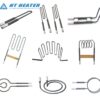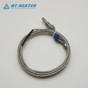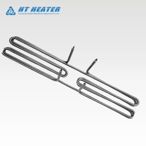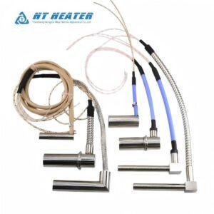
Achieving an isothermal melt temperature across an injection nozzle requires a specialized distributed wattage coil heater to counteract severe localized heat sink losses at both ends of the nozzle assembly. In hot runner injection molding systems, thermal energy is rapidly pulled away from the nozzle ends into the cooler mold manifold block at the rear and the water-cooled cavity plate at the tip. Standard uniform-pitch heaters fail to compensate for this thermal imbalance, creating a saddle-shaped temperature profile with unacceptable cold spots at the extremities and hot spots in the center.
By implementing custom coil heater winding profiles with variable pitch—concentrating higher wattage density at both ends while relaxing pitch in the middle zone—hot runner system engineers and thermodynamic analysts can achieve a flat, highly stable temperature profile. Hongtai Industry Heater manufactures high-precision distributed wattage coil heater assemblies designed specifically to eliminate thermal gradients and prevent polymer degradation or gate freezing in technical molding applications.
1.The Thermodynamics of Nozzle End-Loss Thermal Gradients
In a standard hot runner nozzle, heat dissipation is non-uniform along its longitudinal axis (x). While the center barrel section experiences minimal environmental loss, the nozzle head and tip act as heavy thermal sinks due to direct metal-to-metal contact with cooled mold plates.
The conductive heat loss (q) along the axial position of the nozzle is modeled using Fourier’s Law of Thermal Conduction:
q(x) = −k · A · dT dx
Where:
- q(x) = Axial conductive heat flux (W) at position x
- k = Thermal conductivity of the nozzle steel (W/m·K)
- A = Cross-sectional contact area of the thermal path (m²)
- dT/dx = Temperature gradient along the length of the nozzle (°C/m)
When using a standard uniform heater, the elevated heat flux ($q$) at the ends causes the localized temperature ($T$) to drop sharply. To prevent gate freezing, engineers are forced to raise the overall nozzle temperature, which overheats the middle section and causes thermal degradation, yellowing, or drooling of heat-sensitive polymers (e.g., PET, PC, or PEEK).
2. Mechanics of Custom Coil Heater Winding Profiles
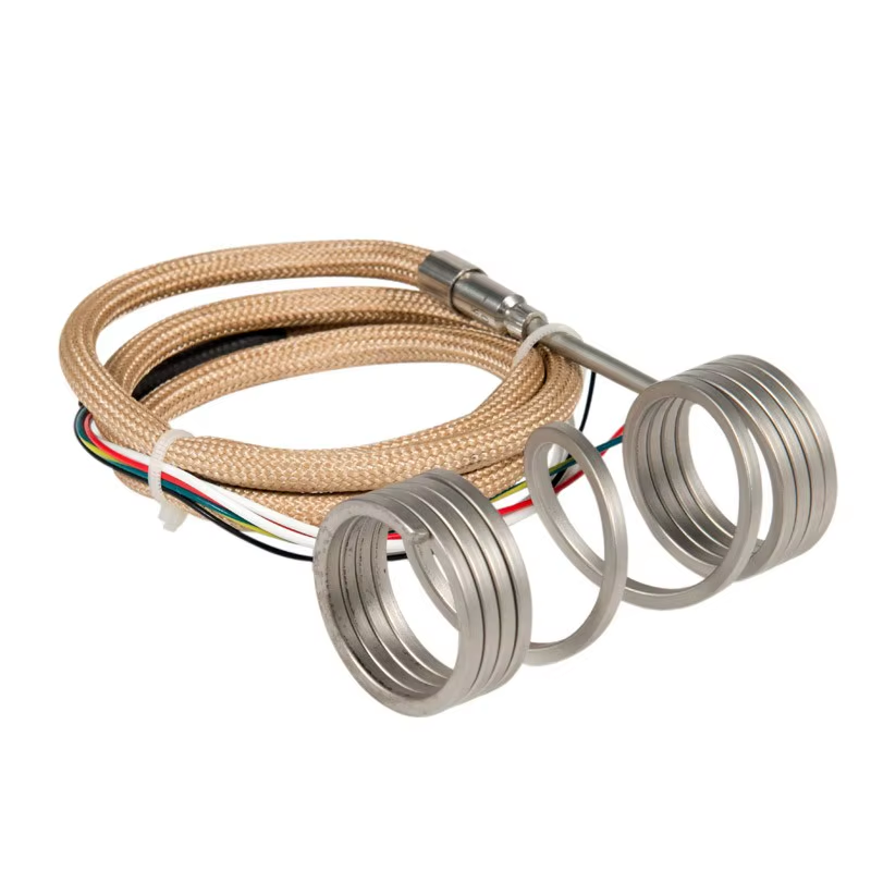
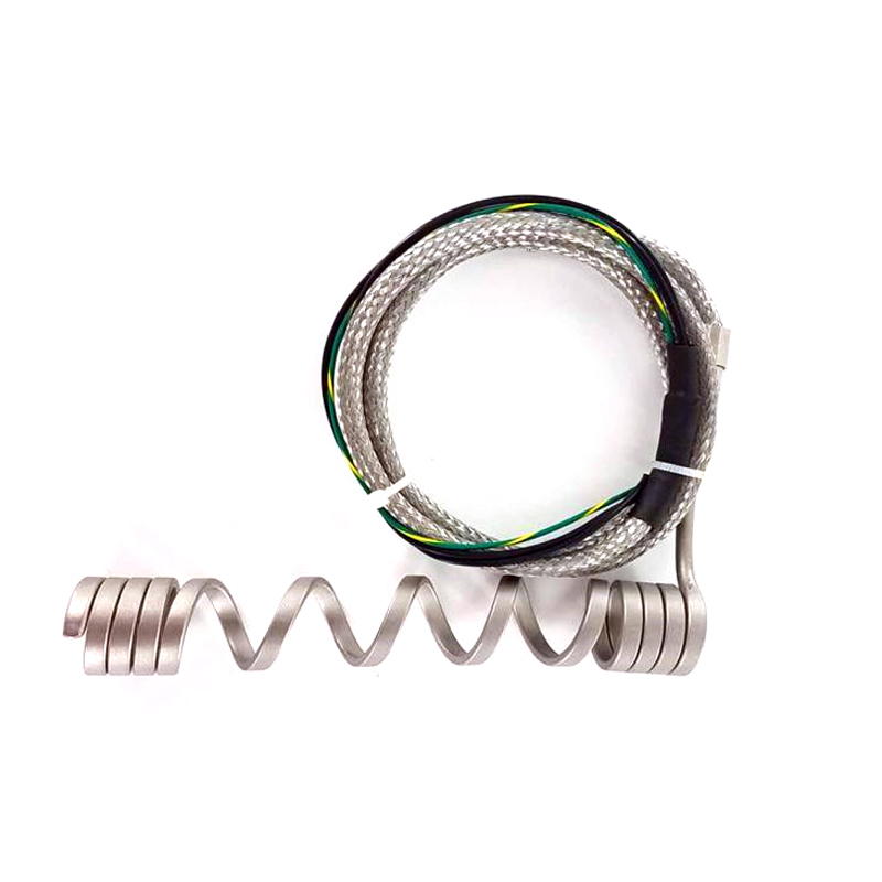
A distributed wattage coil heater resolves thermal non-uniformity by altering the pitch (the axial spacing between adjacent coils) of the resistance wire during manufacturing. Because the power output (P) is directly proportional to the number of active coils per linear millimeter, tightening the pitch increases local watt density.
The linear power density profile (Plinear) across the length of a distributed wattage coil heater is expressed as:
Plinear(x) = V2 · N(x) Rtotal · L
Where:
- Plinear(x) = Power output per unit length at position $x$ (W/mm)
- V = Operating voltage (V)
- N(x) = Number of active coil turns per unit length at position $x$
- Rtotal = Total internal resistance of the heater element (Ω)
- L = Total heated length of the coil (mm)
By engineering a “dense–sparse–dense” winding structure—placing tight coil spacing at both nozzle ends and wider coil spacing through the center—the distributed wattage coil heater delivers high energy where thermal losses are severe, producing an optimized, linear melt temperature profile.
3. Uniform vs. Distributed Wattage Performance Matrix
To evaluate how custom winding geometry impacts thermal performance and molding stability, compare the key operational metrics below:
| Performance Metric | Standard Uniform Coil Heater | Distributed Wattage Coil Heater |
| Winding Pitch Geometry | Constant spacing throughout full length | Variable spacing (Tight ends, wide center) |
| Nozzle Axial Temperature Profile | Parabolic / Saddle curve (Cold ends, hot center) | Flat / Isothermal profile (±1.5°C uniformity) |
| Thermal Loss Compensation | Poor (Requires over-powering nozzle center) | Direct (Tailored energy input matching heat sinks) |
| Resin Degradation Risk | High (Hot spots degrade melt in center zone) | Minimal (Eliminates localized thermal spikes) |
| Gate Freezing & Stringing | Frequent due to tip thermal drop | Eliminated (Sustains target temperature at tip) |
4. Thermocouple Placement for Linear Temperature Control
To achieve optimal closed-loop control with a distributed wattage coil heater, thermal analysts must position the internal or external thermocouple strategically.
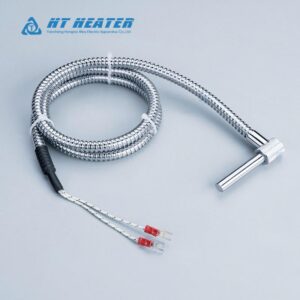
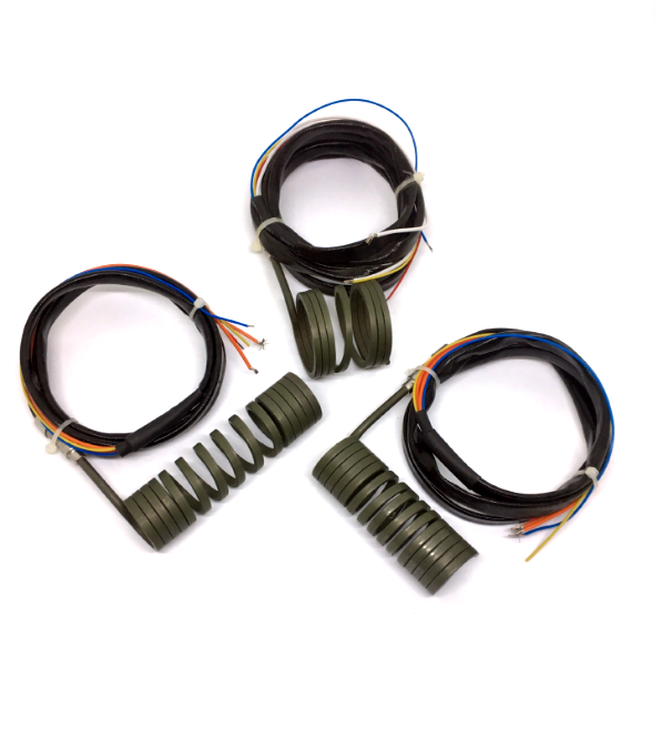
- Integrated Type J / Type K Thermocouples: Positioning an integrated thermocouple in the densely wound head or tip region provides immediate detection of thermal drawdown during high-speed injection cycles.
- Dual-Zone Thermal Management: On long hot runner nozzles (exceeding 150mm), engineers often pair a distributed wattage coil heater with dual TC feedback loops to modulate power output dynamically across separate physical zones.
For material thermodynamic data and thermal simulation guidelines, consult MatWeb Material Property Data and ISO Plastics Engineering Standards.
Custom Winding Engineering from Hongtai Industry Heater
Eliminated temperature fluctuations directly improve part consistency, reduce scrap rates, and shorten injection cycle times. Hongtai Industry Heater specializes in thermal analysis and custom winding engineering, manufacturing each distributed wattage coil heater to match the exact heat loss profile of your hot runner nozzles.
Whether you require square profile elements, Incoloy sheathing, or integrated thermocouple feedback, contact Hongtai Industry Heater‘s thermodynamic engineering team today to optimize your hot runner thermal profiles and request custom CAD prototypes.
B2B Related Technical Resources
- Sheath Metallurgy Selection:Sheath Materials for Hot Runner Coil Heaters: Stainless Steel vs. Nickel
- Cross-Section Selection:Hot Runner Coil Heater Cross Section: Round vs. Square vs. Rectangular
- Thermodynamic Sizing:Cast in Heater kW Calculation: Sizing, Thermal Mass, and Ramp-Up Time
- Surface Contact Resistance: Cast-in Heater Maintenance Guide: Surface Cleaning and Thermal Compound Application
- Quality Inspection & Testing:Quality Control Standards for Cast-in Heaters: Hi-Pot, Insulation, and X-Ray Inspection