Understanding root cast in heater failure causes is critical for facility maintenance engineers and plant after-sales technical support teams striving to eliminate unscheduled machine downtime. When a heavy heating assembly fails, identifying specific cast in heater failure causes—such as open-circuit burnout, warped contact faces, or cracked casting bodies—prevents premature replacement failures. Simply swapping out a damaged component without investigating underlying cast in heater failure causes almost guarantees repeated breakdown under operating conditions. Executing a structured diagnostic protocol allows field technicians to isolate mechanical stress, uneven clamping torque, and thermal overload before installing new units.
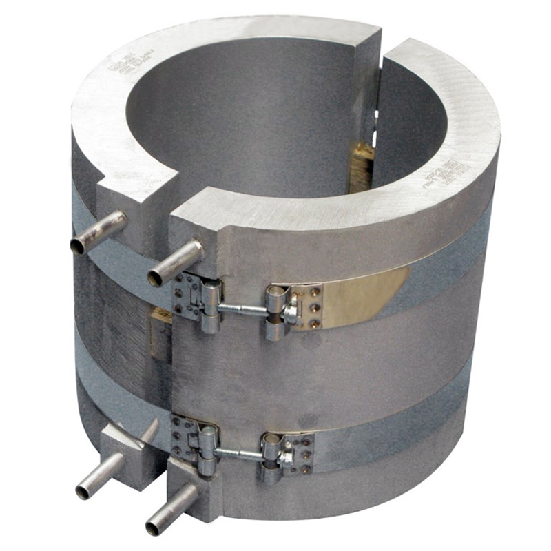
1. Primary Cast in Heater Failure Causes: Physics of Thermal Stress and Warping
Evaluating major cast in heater failure causes requires analyzing how mechanical constraints, differential thermal expansion, and dielectric insulation breakdown interact inside metallic matrices.
According to Fourier’s Law of Thermal Conduction:
When analyzing cast in heater failure causes, field engineers routinely encounter three physical failure mechanisms:
- Uneven Clamping Torque & Thermal Warping: Overtightening or unevenly torquing mounting bolts prevents the casting half from expanding freely during thermal ramp-up. The resulting mechanical binding causes permanent bowing (warping) of the inner bore surface, introducing air gaps (Δx). Trapped air drives internal element temperatures past safe thresholds.
- Thermal Fatigue & Casting Cracking: Rapid thermal cycling combined with internal casting porosity forces the aluminum matrix to expand and contract repeatedly against the embedded tubular heating element. Internal stress concentration leads to visible surface cracks along the casting seam.
- Internal Element Burnout: Excessive watt density or prolonged 100% PID duty cycles cause internal resistance wire temperatures to exceed the melting point of Nichrome 80/20 (>1,100°C), resulting in open-circuit wire failure inside the compacted MgO insulation.
2. Field Diagnostic Checklist for Cast-In Heating Assemblies
When responding to an active zone alarm, maintenance leads should execute this step-by-step diagnostic workflow to isolate internal faults:
| Diagnostic Inspection Step | Physical Observation / Measurement | Primary Root Cause | Corrective Maintenance Action |
| 1. Visual Surface Inspection | Bowed bore surface, uneven gap against barrel | Thermal warping due to uneven clamping torque | Re-machining bore surface or full replacement |
| 2. Sheath Continuity Test | Infinite Resistance (∞ Ω) via Multimeter | Cast aluminum heater element burnout | Replace casting; check PID duty cycle limits |
| 3. Insulation Resistance (Megger) | Resistance < 5 MΩ at 500V DC | Moisture absorption in MgO insulation | Perform thermal bake-out at low voltage |
| 4. Casting Body Examination | Visible hairline fractures along heater paths | Internal gas porosity & extreme thermal shock | Audit casting quality; enforce soft-start ramps |
| 5. Terminal Stud Audit | Loose posts, melted lead wire insulation | Excessive vibration or loose stud torque | Re-terminate lead wires; torque to factory spec |
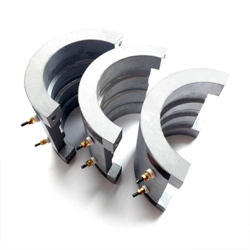
3. Repair Cast in Heater Options vs. Replacement Protocols
When evaluating whether to repair cast in heater components or replace them entirely, plant engineers must assess structural damage severity:
- When Repair is Feasible: Minor surface oxidation, damaged external lead wiring, or moisture absorption inside terminal ends can be repaired on-site. Moisture absorption can be corrected by placing the heater in an industrial bake-out oven at 120°C for 6 to 8 hours to restore dielectric insulation resistance (>100 MΩ).
- When Full Replacement is Mandatory: Internal resistance wire blowouts (cast aluminum heater element burnout), cracked casting matrices, or warped inner bores cannot be reliably re-welded or straightened in the field. Attempting to grind or re-bore a severely warped casting reduces sheath wall thickness, causing rapid secondary burnouts.
To ensure long-term casting integrity and eliminate air voids during original equipment selection, review foundry quality benchmarks in How Porosity Affects Heat Transfer in Cast-in Heating Elements.
4. Preventative Maintenance and System Optimization
To prevent premature failures and maximize the operational lifespan of cast-in heating assemblies:
- Enforce Hot Re-Torque SOP: Always follow a standardized mounting and thermal expansion re-torquing workflow, as outlined in our Band Heater Installation SOP: Preventing Hot Spots and Early Burnouts
- Verify Watt Density Safety Margins: Ensure surface power ratings do not exceed material limits by consulting Understanding Watt Density: The Key to Preventing Premature Band Heater Failure
- Optimize Barrel Cooling Systems: When integrating forced air or liquid cooling channels into extrusion castings, compare system dynamics in Air Cooled Cast in Heater: Extruder Barrel Cooling Guide.
- Standardize Procurement RFQs: Specify precise alloy grades, machining tolerances, and junction configurations by using our guide on How to Specify Custom Cast-in Heaters for Industrial Machinery and compare base materials in Cast-in Heater Material Selection Guide: Aluminum vs. Bronze vs. Iron.
For troubleshooting open-circuit faults across sheet or barrel heating bands, see Troubleshooting 101: 5 Common Causes of Band Heater Burn-Out. For liquid-tight nozzle zones, review Brass Nozzle Heater: Eliminating Plastic Leakage Downtime.
To diagnose electrical faults across ceramic systems, review How Porosity Affects Heat Transfer in Cast-in Heating Elements or consult our primary engineering reference: Industrial Band Heaters: The Ultimate Engineering Guide to Selection, Efficiency & Troubleshooting (2026 Edition).