When commissioning new extrusion lines or troubleshooting underperforming injection molding machines, equipment engineers frequently fall into a critical, yet common, thermodynamic misconception. They operate under the assumption that “higher power equals faster heating and greater machine efficiency.”
When an extruder takes too long to reach its operating setpoint, the reflex is often to procure a replacement band heater with a higher wattage. The inevitable result? The newly installed heating element fails within weeks—or even days—due to internal resistance wire burnout, causing unscheduled downtime that costs exponentially more than the component itself.
This guide demystifies the single most critical physical metric determining the lifespan of an industrial heating element: Watt Density. We will analyze how to precisely calculate required surface loads, deconstruct the physical failure mechanisms of “over-wattage,” and reveal the hard material limits of mica, ceramic, and brass heating systems.
The baseline engineering reality is this: Excessive watt density is the primary cause of premature heating element failure. During the thermal system design phase, a physical balance must be struck between the target heat-up time and the maximum safe watt density for the selected heater material (e.g., Mica $\le$ 3 W/cm², Ceramic $\le$ 6 W/cm²). To accelerate heating, it is mathematically and mechanically preferable to increase the physical surface area of the heating bands rather than blindly escalating the watt density of an individual component.
If you are unsure which material matrix suits your process power requirements, consult our [Ultimate Industrial Band Heaters Guide].
1. Physical Definition: What is Watt Density and How is it Calculated?
The most persistent design blind spot in thermal engineering is focusing solely on “Total Wattage” while completely ignoring the “Heated Area.” A 1000W heater spread over a massive barrel will barely become warm to the touch, while a 1000W heater confined to a 50mm nozzle will melt itself into slag in seconds.
Watt Density is the measurement of heat flux. It quantifies how much electrical power is being converted into thermal energy per unit of active surface area.
The Engineering Formula for Watt Density
Watt density is calculated by dividing the total wattage of the heater by its effective heated area.
Watt Density = {Total Power (W)} / {Effective Heated Area}
- Metric Unit: W/cm² (Watts per square centimeter)
- Imperial Unit: W/in² (Watts per square inch)
Crucial International Conversion: To prevent catastrophic data misinterpretation during cross-border equipment procurement or design, engineers must apply the correct conversion factor:
1 W/cm^2 ≈ 6.45 W/in^2
A specification calling for “30 Watt Density” in North America (W/in²) is a safe, standard load. If a European or Asian supplier misinterprets this as 30 W/cm², the heater will instantly vaporize upon receiving power.
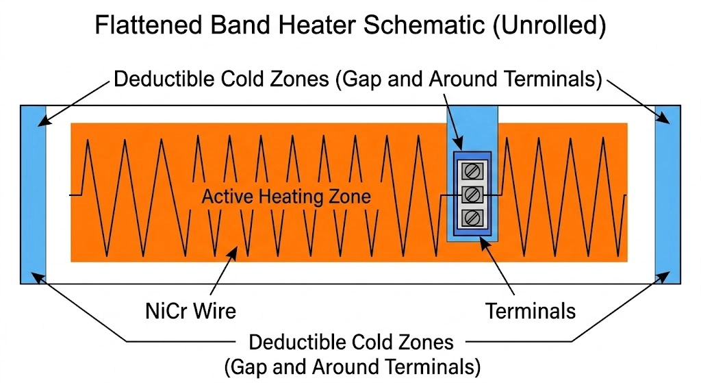
Deduction of the “Cold Zone” in Calculations
A common mathematical error occurs when engineers calculate the area using the simple cylinder surface area formula (Area = π * Diameter * Width). This assumes the entire inner surface of the heater contains resistance wire.
In reality, every industrial band heater possesses “Cold Zones.” These are unheated sections necessary for mechanical clamping and electrical terminations.
- The Gap: The physical space where the two ends of the heater meet and are pulled together by screws or springs.
- The Terminals: The localized area beneath the screw terminals or wire leads where the resistance wire connects to the cold pins.
These areas must be deducted from the total surface area. If the cold zones are not subtracted, the calculated denominator will be artificially large, resulting in a calculated watt density that appears lower (and safer) than it actually is.
Corrected Formula:
WD = {W} / {(π * D * w) – (Area_{gap} + Area_{terminals})}
2. The Death Spiral: Why Excessive Watt Density Destroys Heating Systems
To understand why a heater fails, we must examine the failure process from a microscopic, thermodynamic perspective. A band heater does not “absorb” heat; it generates and transfers it.
Heat “Traffic Jam” and Internal Heat Buildup
Heat transfer obeys Fourier’s Law of Thermal Conduction. The rate at which heat moves from the heater into the machine barrel is limited by the thermal conductivity of the steel and the available contact area.
If the Watt Density is too high, the heater is generating thermal energy faster than the machine barrel can physically absorb it. This creates a thermal “traffic jam.” Because the heat cannot exit the heater efficiently, it accumulates internally.
As a result, the △T (temperature differential) between the internal wire and the external barrel skyrockets. The internal Nickel-Chromium (NiCr) resistance wire will instantly surge past its designed operating temperature, frequently exceeding its melting point of roughly 1200°C – 1400°C. The wire oxidizes rapidly, becomes brittle, and snaps, resulting in an open circuit and total heater failure.
Disaster in Plastic Processing: Polymer Degradation
Excessive watt density does not merely destroy the hardware; it aggressively ruins the product being manufactured.
Even if the heater manages to survive the high surface load, the instantaneous release of extreme thermal energy causes localized “hot spots” on the inner wall of the extruder barrel. When processing heat-sensitive resins like Polyvinyl Chloride (PVC), Polyacetal (POM), or optical-grade Polycarbonate (PC), these localized temperature spikes cause the polymer chains to degrade. The plastic carbonizes, resulting in yellowing, black spots, structural weakness in the molded part, and highly corrosive outgassing that damages the screw and barrel.
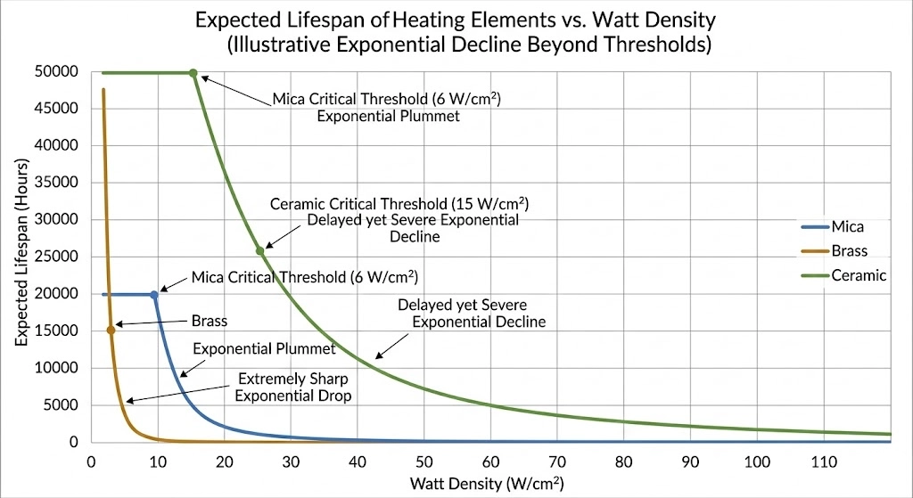
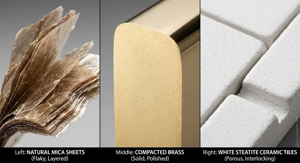
3. Material Physical Ceilings: The Limits of Mica, Brass, and Ceramics
Because different insulation materials possess distinct thermal conductivity rates and dielectric breakdown thresholds, the safe Watt Density limit is strictly dictated by the material matrix of the heater. Specifying beyond these red lines guarantees failure.
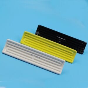
Economy Mica: ≤ 3 W/cm² (20 W/in²)
Mica band heaters represent the economic standard for general-purpose molding. However, the phlogopite or muscovite mica sheets rely on organic binders to maintain their structural integrity.
- The Limit: When surface loads exceed 3 W/cm², the internal heat cannot dissipate rapidly enough through the stainless steel sheath.
- The Failure Mode: At internal temperatures exceeding 340°C, the mica binders begin to volatilize and burn away. The mica turns into a conductive, flaky ash. Once the dielectric strength is lost, the live resistance wire arcs directly to the grounded metal sheath.
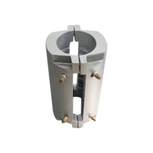
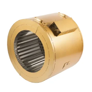
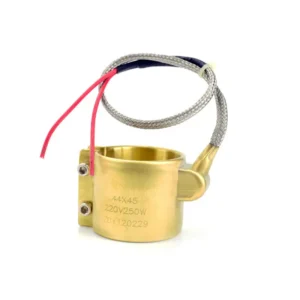
Sealed Brass: $≤ 5 W/cm² (32 W/in²)
Brass sealed nozzle heaters are designed for the high-pressure, space-constrained nozzle zones of injection molding machines.
- The Limit: Brass possesses a highly superior thermal conductivity compared to stainless steel. Furthermore, Hongtai manufactures these heaters using a high-pressure compaction process that eliminates internal air voids.
- The Advantage: Because heat transfers so efficiently from the wire, through the compacted mica, and out through the brass shell, these heaters can safely sustain up to 5 W/cm² without internal heat buildup.
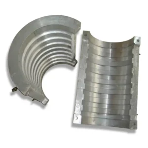
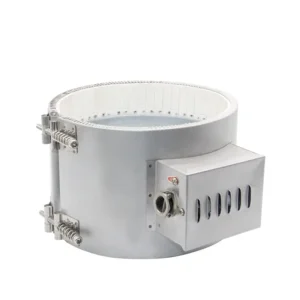
Thermal Ceramic: ≤ 6 W/cm² (39 W/in²)
Ceramic band heaters are the heavy-duty workhorses required for high-load extruders and high-temperature engineering plastics (like PEEK or Ultem).
- The Limit: The internal resistance coils are threaded through interlocking steatite ceramic knuckles. Steatite contains no organic binders to burn off and exhibits immense dielectric strength even at extreme temperatures.
- The Advantage: This material architecture allows ceramic heaters to safely support watt densities up to 6 W/cm² and external operating temperatures of 600°C.
4. Practical Selection: How to Safely Shorten Machine Warm-Up Time?
When an equipment operator states, “My machine must reach 250°C within 20 minutes to meet production schedules, but engineering guidelines state I cannot increase the watt density. What is the solution?”
The solution relies on geometric optimization and thermal conservation, not raw power escalation.
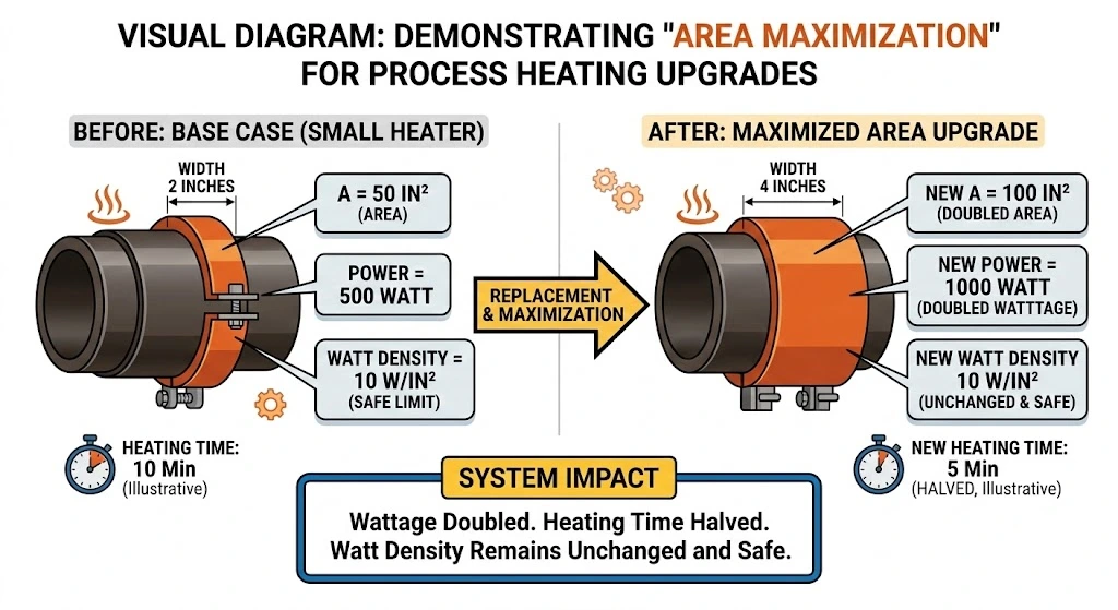
Maximize Surface Area
If a process requires more total wattage to overcome the thermal mass of a large extruder barrel, you must increase the total power (W) by simultaneously increasing the heated area (A), thereby keeping the Watt Density constant.
- Engineering Strategy: Specify wider heating bands. If space along the barrel permits, replacing a 50mm wide heater with a 100mm wide heater allows you to double the total wattage input while maintaining the exact same, safe watt density. Alternatively, add more individual heating bands along the available barrel zones.
Utilizing Nano and Insulation Technologies (Reduce Heat Loss)
If physical space on the barrel is strictly limited, the focus must shift from generating more heat to losing less heat.
- Engineering Strategy: Standard uninsulated heaters lose up to 40% of their generated energy to the ambient workshop air. By upgrading to [Nano Band Heaters]—which utilize aerospace aerogel insulation—or by installing custom thermal insulation blankets over existing ceramic bands, you block the outward dissipation of energy.
- The Result: 100% of the generated wattage is forced into the steel barrel. This approach can accelerate machine heating rates by 20% to 30% without altering the electrical input power or risking the watt density limits of the element.
| Heating Element Material | Recommended Max Watt Density (W/cm²) | Recommended Max Watt Density (W/in²) | Typical Operating Temp Limit |
|---|---|---|---|
| Mica Band Heater | ≤ 3 W/cm² | ≤ 20 W/in² | < 340°C |
| Brass Sealed Nozzle | ≤ 5 W/cm² | ≤ 32 W/in² | < 340°C |
| Ceramic Band Heater | ≤ 6 W/cm² | ≤ 39 W/in² | < 600°C |
5. The Amplification Effect of Poor Contact: The Deadly Interaction Between Installation and Watt Density
An engineering design can be mathematically flawless on paper, yet the components will still catastrophically fail on the factory floor if installation physics are ignored.
Air Gaps Are the Ultimate Insulators
The thermal conductivity of steel is approximately 45 W/m·K. The thermal conductivity of air is roughly 0.026 W/m·K. Air is an exceptionally powerful thermal insulator.
When a heater is operating near its upper surface load limits—such as a ceramic band running at 5.5 W/cm²—it requires absolute, 100% surface contact with the metal barrel to dump its heat. If a maintenance technician fails to properly torque the clamping screws, or if there is polymerized plastic residue on the barrel, a microscopic air gap (even 0.1mm) forms between the heater and the machine.
This tiny air gap completely halts conduction in that specific sector. The heat backs up into the heater core immediately, triggering a localized “hot spot” that melts the wire in a matter of hours. Proper mechanical clamping is the only way to ensure the calculated watt density functions in reality.
To ensure your maintenance team follows proper torquing and re-tightening procedures, refer to our comprehensive [Installation SOP].
6. Troubleshooting: How to Identify “Overload” Failures?
When a heater fails, the physical evidence left behind on the component allows maintenance personnel to diagnose whether the root cause was a voltage spike, chemical contamination, or a watt density overload.
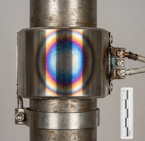
Post-Mortem Signs of Over-Wattage
- Sheath Discoloration (Oxidation): Inspect the external stainless steel sheath of the failed heater. If there are visible blue, purple, or rainbow-colored oxidation rings—particularly concentrated in one area—this indicates the metal surface was subjected to extreme heat pooling far beyond its 400°C design parameter. This is a classic sign that the watt density exceeded the heat transfer rate.
- Melted Beads on the Resistance Wire: Upon disassembling a failed mica or ceramic heater, examine the broken ends of the NiCr resistance wire. A failure caused by mechanical fatigue or vibration will show a clean, jagged snap. A failure caused by excessive watt density will exhibit melted, spherical “beads” or slag at the tips of the break, proving the wire reached its absolute melting point due to thermal overload.
7. Engineer’s Conclusion
The TCO Priority Principle
In B2B thermal system design, the Total Cost of Ownership (TCO) priority must always favor equipment longevity over marginal gains in startup speed.
The physical rule of thumb is unforgiving: Reducing the watt density of a heating element by just 10% will typically double the operational lifespan of that component. During the initial CAD design phase of any extrusion or molding equipment, allocating sufficient physical space on the barrel to accommodate larger, lower-watt-density heating elements is a golden rule that guarantees years of uninterrupted production. Do not sacrifice physical space at the expense of thermodynamic stability.
Frequently Asked Questions
What is a safe watt density for a mica band heater?
For maximum lifespan, a standard mica band heater should not exceed a watt density of 3 W/cm² (approximately 20 W/in²). Exceeding this limit causes internal heat buildup that quickly degrades the mica insulation and melts the internal resistance wire.
How do I calculate the watt density of my band heater?
You divide the total wattage by the effective heated area. The formula is: Total Wattage / [(Inner Diameter × 3.14 × Width) – Cold Zones]. Always remember to mathematically subtract the unheated areas, such as the clamping gap and the terminal connection footprints, to obtain an accurate load calculation.
Can I use a high watt density heater to heat up my extruder faster?
It is highly discouraged to blindly increase watt density. While a higher watt density provides more raw power, if the plastic resin and the metal barrel cannot absorb the heat fast enough, the heater will experience thermal overload and burn out prematurely. Instead of increasing watt density, utilize wider band heaters to increase total wattage safely, or add aerospace insulation to minimize ambient heat loss.
Why did my high watt density ceramic heater burn out with hot spots?
High watt density ceramic heaters (operating up to 6 W/cm²) transfer massive amounts of thermal energy and require flawless, 100% surface contact with the metal barrel. If the heater is not clamped tightly enough, or if debris prevents a flush fit, tiny air gaps form. Because air acts as an insulator, it traps the heat inside the heater’s ceramic core, causing localized “hot spots” that quickly destroy the internal heating coil.