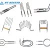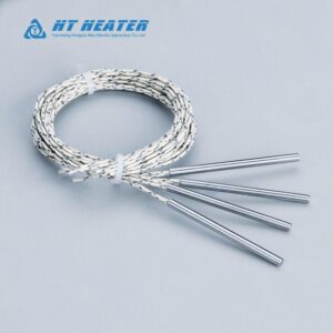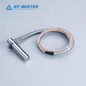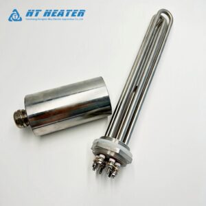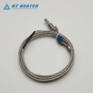
Installing a coil heater with built-in thermocouple delivers precise closed-loop temperature control in compact hot runner cavities without separate nozzle drilling. Matching the right Type J or K calibration with an optimal axial or radial lead exit geometry prevents wiring fatigue and ensures long-term sensing accuracy. Hongtai Industry Heater manufactures heavy-duty integrated coil heaters engineered to withstand continuous thermal cycling and extreme injection molding pressures.
1. Thermocouple Calibration Dynamics: Type J vs. Type K
When specifying a coil heater with built-in thermocouple, engineers must select the thermoelectric calibration that matches their operating temperature range and PID controller requirements. The generated thermoelectric voltage ($V$) is defined by the Seebeck effect equation below:
V = S · ΔT
Where:
- V = Electromotive force / voltage generated (mV)
- S = Seebeck coefficient of the thermocouple alloy pair (µV/°C)
- ΔT = Temperature gradient between the sensing junction and reference junction (°C)
Type J Thermocouple (Iron-Constantan)
- Seebeck Coefficient: ~50 to 55 µV/°C at injection molding temperatures.
- Temperature Range: Effective up to 760°C (1400°F), with optimal accuracy below 370°C (700°F).
- Application Suitability: A hot runner type J thermocouple is the universal standard in North America and Europe for commodity resin molding (PP, PE, PS, ABS). Its higher sensitivity (µV/°C output) provides superior signal-to-noise ratio and rapid PID loop response at standard molding temperatures.
Type K Thermocouple (Chromel-Alumel)
- Seebeck Coefficient: ~40 to 42 µV/°C at injection molding temperatures.
- Temperature Range: Suitable for continuous operation up to 1260°C (2300°F).
- Application Suitability: Ideal for processing high-temperature engineering polymers (PEEK, PEI, PPS) operating above 350°C. Type K offers excellent oxidation resistance at elevated temperatures, though its lower output voltage requires well-shielded PID controller inputs.
2. Lead Exit Configurations: Axial (Back Exit) vs. Radial (Side Exit)
Choosing the correct coil heater wire exit geometry is crucial to prevent mechanical pinching, tight bend stress, and conductor wire fracture during mold assembly and maintenance.
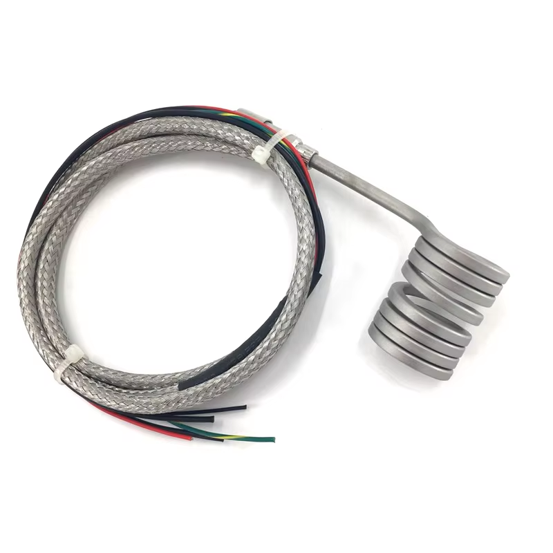
Axial Back Exit (Rear Exit)
In an axial exit configuration, the power lead wires and thermocouple leads exit directly out the back of the heater sheath, running parallel to the nozzle’s central axis.
- Key Advantage: Minimizes the heater’s radial profile, making it indispensable for deep mold cavity pockets, tight center-to-center nozzle spacing, and compact manifold channels.
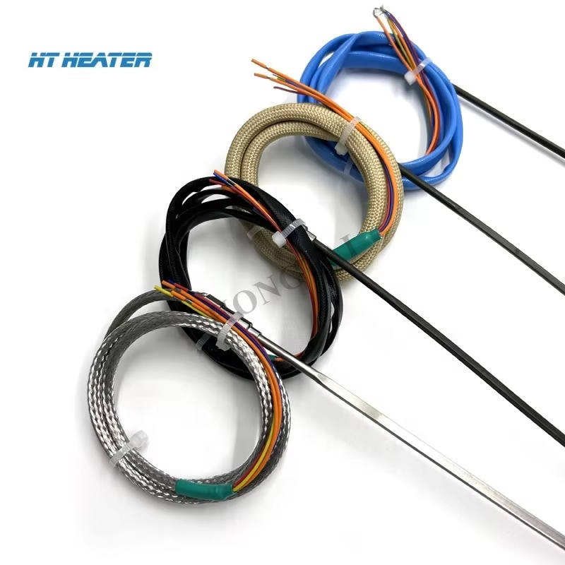
- Protection Strategy: Axial back exits are typically reinforced with stainless steel flexible armor or heavy-duty wire braid to absorb longitudinal strain when the nozzle expands thermally against the manifold.
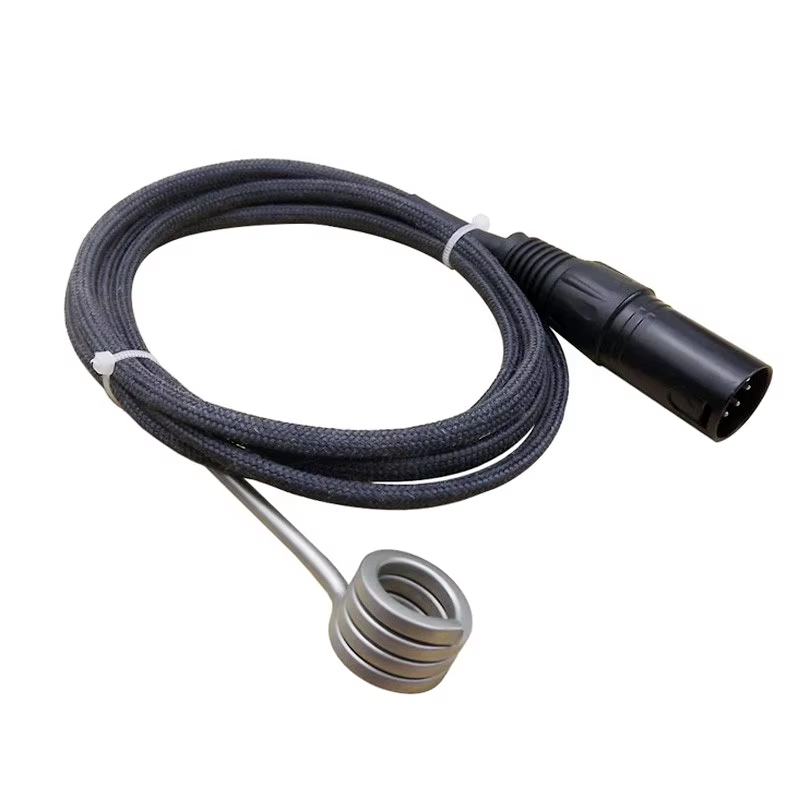
Radial Side Exit (90° Perpendicular Exit)
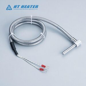
In a radial exit configuration, leads exit perpendicular to the body of the coil heater with built-in thermocouple.
- Key Advantage: Provides an ultra-low clearance profile along the nozzle’s length, ideal when rear clearance above the nozzle head is obstructed by mold plates or hydraulic lines.
- Protection Strategy: Side exits require high-flexibility fiberglass sleeving and integrated anti-kink spring relief coils to prevent sharp 90-degree bend stress during wiring routing.
3. Grounded vs. Ungrounded Thermocouple Junctions
To optimize response time and noise immunity in a coil heater with built-in thermocouple, electrical engineers must select the internal junction grounding mode:
| Junction Type | Internal Construction | Thermal Response Speed | Electrical Noise Immunity | Best Use Case |
| Grounded Junction | Thermocouple wire welded directly to inner sheath metal | Fastest (< 0.2 seconds) | Moderate (Susceptible to ground loops) | High-speed molding with isolated PID controllers. |
| Ungrounded Junction | Sensing tip isolated from sheath by compacted MgO powder | Standard (~ 0.5 seconds) | Maximum (Complete electrical isolation) | Multi-zone hot runners with complex PID systems. |
4. B2B Selection Matrix: Thermocouple & Wire Exit Options
To ensure your coil heater with built-in thermocouple matches your mold routing layout and temperature controller specifications, consult the evaluation matrix below:
| Configuration Parameter | Option A | Option B | Engineering Selection Criteria |
| Thermocouple Calibration | Type J (Fe-CuNi) | Type K (NiCr-NiAl) | Select Type J for standard molding (<370°C); Type K for high-temp resins (>370°C). |
| Wire Exit Orientation | Axial (Back Exit) | Radial (Side Exit) | Use Axial for tight pocket diameters; Radial for low top-plate clearance. |
| Sheath Strain Relief | SS Armor Cable | Spring Strain Relief | Armor cable resists crushing in wire channels; Springs protect against flexing fatigue. |
For detailed thermocouple output tables and EMF standards, reference MatWeb Material Property Data and ISO Temperature Sensor Guidelines.
Custom Sensor Integration from Hongtai Industry Heater
Selecting the proper sensor calibration and wire exit geometry eliminates false PID alarms, protects signal integrity, and prevents costly mold downtime caused by wire breakage. Hongtai Industry Heater builds custom coil heater with built-in thermocouple assemblies tailored to your exact nozzle dimensions, lead length requirements, and wire routing preferences.
Whether you require axial back-exit heaters with armor cabling or square-profile Type J units, contact Hongtai Industry Heater‘s electrical engineering team today for technical consultation and rapid prototype manufacturing.
B2B Related Technical Resources
- Thermal Distribution Design: Distributed Wattage Coil Heater Design & Temperature Profiles
- Sheath Metallurgy Selection:Sheath Materials for Hot Runner Coil Heaters: Stainless Steel vs. Nickel
- Cross-Section Selection:Hot Runner Coil Heater Cross Section: Round vs. Square vs. Rectangular
- Thermodynamic Sizing:Cast in Heater kW Calculation: Sizing, Thermal Mass, and Ramp-Up Time
- Quality Inspection & Testing:Quality Control Standards for Cast-in Heaters: Hi-Pot, Insulation, and X-Ray Inspection