Ceramic Infrared Heaters
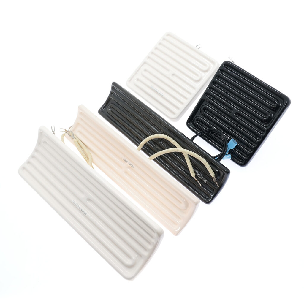
Ceramic Infrared Heater specification for instrumentation engineers and junior designers requires much more than just knowing the target temperature of your process. The most frequent cause of catastrophic element failure—where the internal resistance wire melts, or the ceramic body fractures under severe thermal stress—is an improperly calculated watt density.
When you force excessive electrical power into a confined surface area, the internal temperatures rapidly exceed the material’s structural and thermal limits. This comprehensive engineering guide provides the standardized formulas and thermodynamic principles necessary to understand how to calculate watt density, optimize your infrared heater wattage, and prevent premature burnout in complex industrial thermal systems.
1. The Physics Behind Surface Load and Thermal Flux
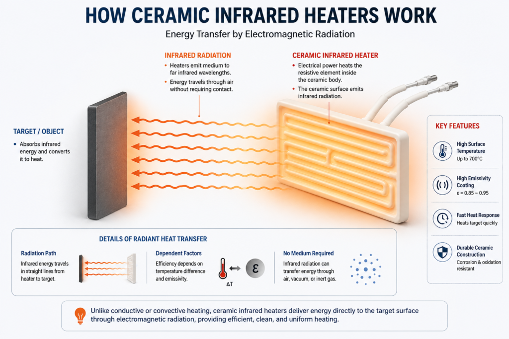
In industrial thermal dynamics, watt density is the critical measure of heat flux. It represents the rate of electrical power dissipation acting upon a specific active surface area. Unlike conduction or convection heating, a Ceramic Infrared Heater transfers energy primarily through electromagnetic radiation. The efficiency of this energy transfer is dictated by the temperature differential between the emitter and the target, as well as the emissivity of the ceramic glaze.
If the watt density is mathematically too high, the heater generates thermal energy internally faster than it can radiate it outward into the surrounding environment. This energy bottleneck causes the internal core temperature to spike dangerously. The embedded nickel-chrome (Ni-Cr) or iron-chromium-aluminum (Fe-Cr-Al) resistance coil will begin to oxidize rapidly, increasing its electrical resistance, which in turn generates even more localized heat. Eventually, this feedback loop leads to an open circuit or causes the refractory ceramic matrix to suffer from thermal shock and physical fracturing.
2. The Standardized Engineering Formula: How to Calculate Watt Density
To prevent these failures, junior designers must verify the thermal flux before finalizing any component specification or submitting an RFQ. Knowing exactly how to calculate watt density is the first line of defense. The standardized equation used across the industrial heating sector is straightforward:
Wd = P/A
- Wd = Watt Density (expressed in W/cm2 or W/in2)
- P = Total infrared heater wattage (expressed in Watts)
- A = Effective emitting surface area (expressed in cm2 or in2)
Critical Engineering Note: A common mistake made by novice engineers is using the total physical dimensions of the heater for the area (A). You must only include the actively heated surface area. Do not factor in unheated mounting studs, cold pins, non-radiating side walls, or terminal enclosures. Including these inactive zones will artificially lower your calculated density, leading you to incorrectly believe a dangerously overpowered heater is within safe operating limits.
Step-by-Step Calculation Example
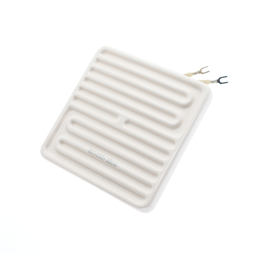
Let us assume you are designing a thermoforming oven and have selected a standard square flat emitter.
- Determine Physical Dimensions: The radiating face measures 122 mm by 122 mm.
- Calculate Effective Area (A): 12.2cm x 12.2cm = 148.84cm2.
- Identify Total Power (P): Your process requires an infrared heater wattage of 650W per element to meet cycle times.
- Execute the Formula: 650 W / 148.84 cm2 = 4.36 W/cm2.
3. Optimizing Infrared Heater Wattage for Process Loads
Before you can calculate the watt density, you must first establish the correct power requirement. Over-specifying the infrared heater wattage “just to be safe” or to achieve artificially fast heat-up times is a dangerous practice that guarantees high surface loads.
Your total power calculation should be grounded in the thermodynamic requirements of your target material. You must calculate the sensible heat required to raise the mass of your product to the target temperature within your desired cycle time:
- \( P_{required} \): Watts
- \( m \):Mass
- \( C_p \):Specific Heat Capacity
- \( \Delta T \): Temperature Rise
- \( t \):Time
- \( \eta \): System Efficiency
Where m is the mass, Cp is the specific heat capacity of the material, ΔT is the required temperature rise, t is the time available, and η is the system efficiency (accounting for radiant losses). Only after determining this baseline wattage should you select the physical size of your Ceramic Infrared Heater to ensure the resulting watt density falls safely within operational parameters.
Safe Operating Thresholds for Ceramic Elements
Once you know how to calculate watt density, you must compare your result against the material tolerances of ceramic heating elements. Exceeding these limits will trap heat inside the refractory matrix, rapidly degrading the internal nickel-chrome resistance wire.
| Watt Density Limit (W/cm²) | Operating Condition | System Recommendation |
| 2.0 – 4.5 W/cm² | Safe / Standard | Ideal for continuous, 24/7 steady-state operations. Maximum lifespan. |
| 4.5 – 6.0 W/cm² | High Load | Requires strict PID temperature control and built-in thermocouples. |
| > 6.0 W/cm² | Danger Zone | High risk of thermal shock and premature burnout. Redesign the layout to increase surface area. |
5. System-Level Burnout Prevention Strategies
Even with a perfectly calculated watt density, system-level design flaws can still induce premature failure. Instrumentation engineers must implement the following safeguards:
Precision Control: Never use simple ON/OFF mechanical contactors for high-density elements. Employ Solid State Relays (SSRs) paired with PID controllers featuring fast cycle times (e.g., 1-second pulsing) to maintain stable core temperatures without aggressive thermal cycling.
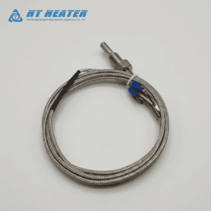
Integrated Thermocouples: Specify your Ceramic Infrared Heater with a built-in Type K or Type J thermocouple positioned directly against the internal resistance coil. This provides real-time feedback to your PID controller, preventing the core from exceeding safe limits regardless of ambient environmental conditions.
Reflector Spacing: Ensure the heating array is mounted with adequate standoff distance from its aluminized steel or stainless steel reflectors. Insufficient spacing traps convective heat behind the element, drastically raising the effective operating temperature and defeating the safety margins of your initial watt density calculations.