Most delays and field fit-up failures in custom furnace heating elements procurement happen because critical thermal, dimensional, or electrical details are missing from the initial Request for Quote (RFQ). Sending a vague request like “1200°C furnace, 30 kW” risks cold ends overheating inside wall insulation, mismatched transformer taps, or rapid chemical attack.
This concise guide gives purchasing managers, furnace OEMs, and maintenance leads an actionable heating element RFQ framework to lock in furnace heating element specifications on the first pass.
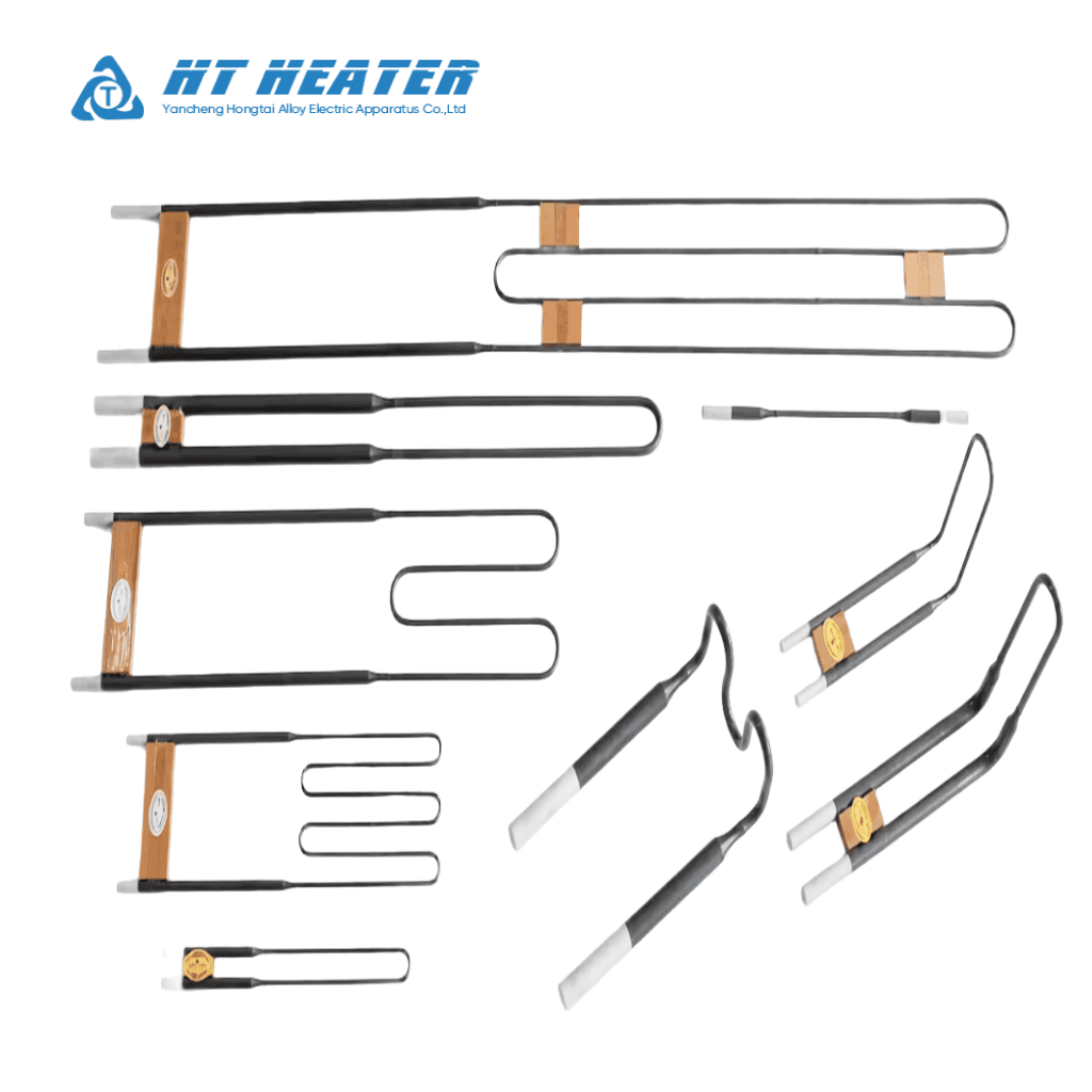
1. Element Types & Critical Dimensional Boundaries
Start by matching the element material and geometry to your chamber layout, then verify exact dimensional boundaries with your industrial furnace heater manufacturer:
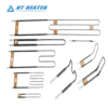
Custom MoSi₂ Heaters: U-, W-, L-, and multi-shank elements welded from smaller heating zones (d1) and thicker cold shanks (d2) for ultra-high oxidizing temperatures. (See MoSi₂ heating element grades and shapes).
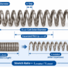
Metallic Alloys (NiCr / FeCrAl): Open helical coils, zig-zag ribbons, ceramic bobbin heaters, and tubular elements for medium-to-high temperatures. (See NiCr heating wire alloy selection).
Custom SiC Heaters: Equal-diameter (ED), dumbbell/thick-end (GD), U-type, W-type, and spiral grooved (SG/DR) rods for rigid high-temperature mounting. (See silicon carbide heating element types).
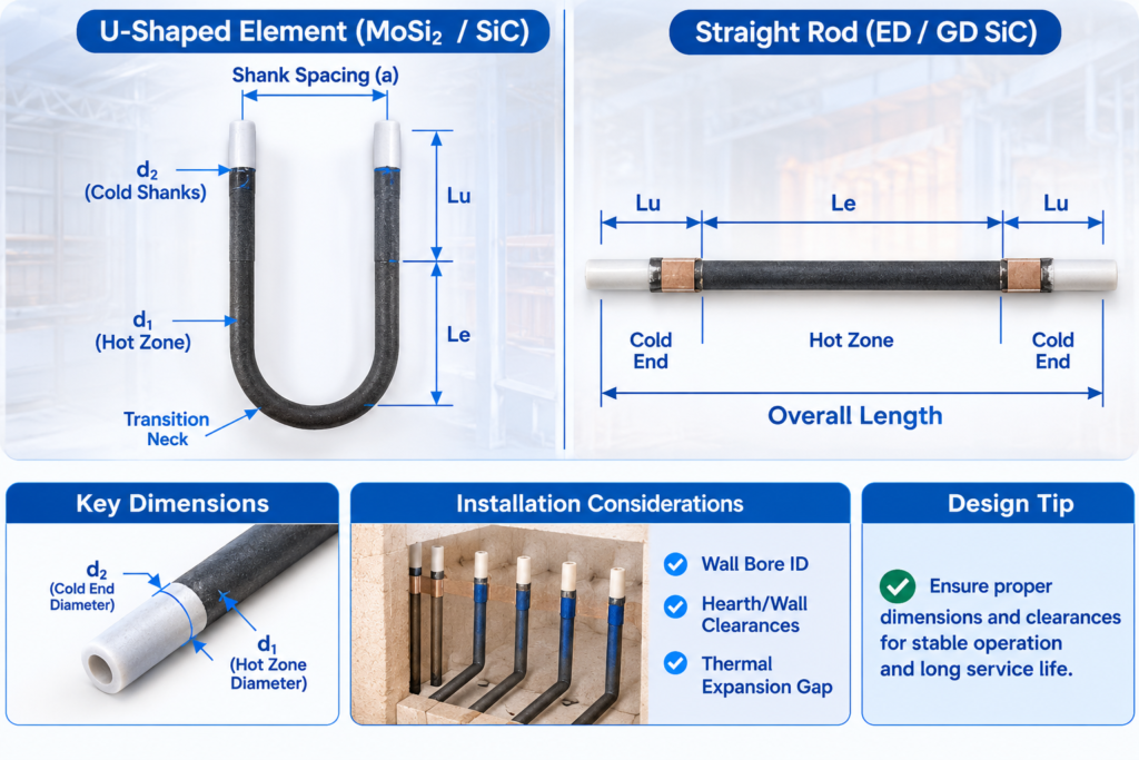
Key Dimensional Rules
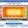
- Hot Zone (Le) & Transition Neck: The entire heating zone—including any tapered weld neck—must sit completely inside the open chamber, clear of the hot refractory wall face.
- Cold End Length (Lu): Size Lu based on total wall/roof thickness, external clamp dimensions, terminal temperature limits, and thermal expansion/creep allowance—never by guessing a fixed overhang.
- Mounting & Clearances: Confirm wall bore inner diameters, orientation (vertical hanging, horizontal pass-through, or wall grooves), and minimum distances to the hearth, walls, and workload.
2.Electrical, Thermal & Atmosphere Specifications
Total zone kW alone is not enough to build an element. Include these three boundary sets in every RFQ:
2.1 Electrical & Power Control Compatibility
- Per-Element Load: Specify element count per zone, phase configuration (1-phase, 3-phase Wye/Delta), and series/parallel wiring to establish per-element voltage (V), current (I), and wattage (W).
- Material-Specific Control Needs:
- NiCr / FeCrAl: Provide 20°C cold resistance and operating temperature so the factory can apply the correct temperature correction factor (Ct). (See heating wire resistance calculation).
- MoSi₂: Because cold resistance is much lower than hot resistance (exact ratios vary by grade/size per manufacturer curves), confirm your SCR controller’s phase-angle current limit and maximum startup amperage. (See MoSi₂ startup current and SCR control).
- SiC: State your transformer’s secondary voltage tap range to ensure sufficient reserve voltage as SiC resistance rises with age.
2.2 Thermal Duty & Atmosphere Disclosure
- Chamber vs. Element Temperature: Element surface temperature always runs hotter than the furnace setpoint to drive heat transfer. Specify normal/peak chamber temperatures, ramp rate, soak time, and batch load weight.
- Exact Atmosphere Chemistry: Do not simply write “nitrogen” or “vacuum.” Specify gas ratios (e.g., 95% N2 / 5% H2), dew point, operating pressure/vacuum level, and any process volatiles (sulfur, halogens, lead, alkali vapors, or binder burnout oils) across all cycle stages.
3. Retrofit & Replacement Projects: Matching Existing Systems
When sourcing replacement elements for an operating furnace, combining dimensional measurements with live electrical data prevents circuit imbalance:
- Live Operating V/I Measurements: Record steady-state transformer secondary voltage (V_run) and live branch amperage (I_run) at a documented reference chamber temperature.
- SiC Resistance Grouping Across Topologies: Because SiC elements gradually increase in resistance with age, mixing mismatched resistances skews power distribution—overloading low-resistance rods in parallel circuits or over-voltaging high-resistance rods in series strings. When replacing partial SiC banks, measure the operating resistance of remaining rods and confirm whether your power supply taps need adjustment after installation. (See SiC element resistance matching and furnace heating element troubleshooting).
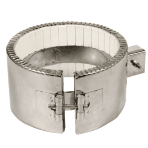
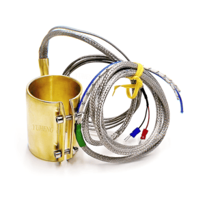
- Accessory & Hardware Compatibility: Specify whether replacement orders require matching aluminum terminal braids, stainless steel spring clamps, ceramic sleeves, or refractory holder blocks.
4. Quality Assurance & OEM Approval Workflow
For OEM builds and critical production lines, lock in inspection criteria before production begins:
RFQ Submission → Engineering Review → Signed Approval Drawing → Prototype / Sample → First-Article Inspection → Batch Delivery
- Dimensional & Electrical Checks: Verify geometric tolerances against the signed approval drawing, room-temperature resistance per element, SiC resistance-group sorting, and insulation/hipot testing where applicable.
- Documentation: Request Material Test Reports (MTRs), batch resistance inspection logs, and lot traceability markings.
5.Master OEM RFQ Checklist
Attach this checklist to your inquiry package to speed up quoting and eliminate back-and-forth emails:
| Category | Required RFQ Fields | Example / Procurement Note |
| 1. Project & Print | New OEM vs. retrofit, drawing rev & photos | Attach 2D print (mm) + photos of existing setup/markings |
| 2. Element Type | Material grade & physical shape | e.g., NiCr 80/20 coil / Grade 1800 U-type MoSi2 / ED SiC rod |
| 3. Dimensions | Le, Lu, diameters (OD or d1/d2) & spacing (a) | Include transition neck lengths and overall length tolerances |
| 4. Mounting | Wall thickness, orientation & clearances | e.g., 300 mm roof thickness; vertical hang; 60 mm wall gap |
| 5. Electricals | Per-element V, W, nominal ohms & ref temp | State test temp for nominal ohms (e.g., 20°C cold resistance) |
| 6. Power Supply | Elements/zone, series/parallel, SCR/transformer | e.g., 3-phase 380V, 40–180V tapped transformer + phase-angle SCR |
| 7. Thermal Duty | Normal/peak chamber temp, ramp & load mass | e.g., 1550°C normal / 1600°C peak; 5°C/min ramp; 250 kg load |
| 8. Atmosphere | Gas composition, dew point, pressure & volatiles | e.g., Clean static air (no sulfur/halogens); or 90% N2 / 10% H2 |
| 9. Retrofit & QA | Live V/I data, SiC resistance group & test docs | Include existing SiC resistance range; request MTR & ohm log |
| 10. Commercial | Accessories (clamps/braids), qty & lead time | e.g., 12 elements + 24 clamp/braid kits; sample before batch |
Partner with Hongtai for Precision Custom Furnace Heating Elements
Hongtai Heater Factory upplies global furnace OEMs and plant maintenance teams with custom-wound NiCr and FeCrAl helical coils and ribbon elements, resistance-matched custom SiC heaters, high-purity custom MoSi₂ heaters, and complete mounting kits (aluminum braids, spring clamps, and high-alumina ceramic insulators).
- Consult our Engineers: Send your wiring schematics to the Hongtai Heater Factory technical team for a free design review.
- Visit Us:: www.hongtai-heater.com