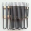
In the electrical system design of ultra-high-temperature industrial furnaces (1500°C–1750°C), molybdenum disilicide (MoSi2) is widely recognized as the premier non-aging heating element due to the self-healing quartz glass (SiO2) film that forms on its surface. However, electrical engineers and commissioning technicians often face severe startup issues when first energizing a MoSi2 load: instantaneous circuit breaker trips, blown semiconductor fuses, or fractured cold-end terminals caused by intense electrodynamic forces.
These failures stem directly from the material’s steep, physical Positive Temperature Coefficient (PTC), which creates a vast difference between room-temperature and operating-temperature resistance. A reliable MoSi2 heating element power control system requires precise coordination among step-down transformer ratios, phase-angle SCR firing algorithms, closed-loop current limiting, and circuit topology. If you are still finalizing element geometry and temperature grade selection, consult our introductory guide: MoSi2 Heating Elements: Grades, Shapes & High-Temperature Applications.

1.MoSi₂ Cold Resistance vs. Hot Resistance: Why Startup Current Matters
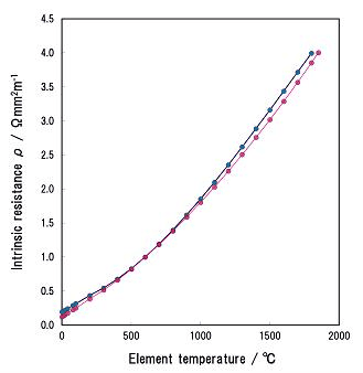
Unlike nickel-chromium alloys (which exhibit relatively flat resistance profiles) or silicon carbide (which features an initial negative temperature coefficient as detailed in SiC Heating Element Resistance: Aging, Power Control & Replacement), MoSi2 exhibits a steep, linear Positive Temperature Coefficient (PTC) from ambient temperature up to 1800°C:
- The Cold-to-Hot Resistance Disparity: The electrical resistance of a MoSi2 element at normal operating temperatures (1500°C–1700°C), denoted as R_hot, is typically 10 to 14 times higher than its room-temperature (20°C) cold resistance, MoSi2 cold resistance (R_cold). The exact ratio depends on element diameter, hot zone length, and the specific grade curve.
- Uncontrolled Inrush Current: According to Ohm’s Law (I = V / R), applying full operating voltage to a cold furnace bank produces a theoretical MoSi2 startup current exceeding ten times the rated full-load operating current:
Icold_inrush = Vrated / Rcold ≈ 10–14 × Ihot
- Mechanical and Electrical Damage: This massive surge causes supply voltage sags, trips magnetic circuit breakers, and risks transformer core saturation. Furthermore, the alternating current generates severe electrodynamic repulsive forces (Lorentz forces) between parallel cold-end shanks, causing mechanical fatigue and snapping brittle cermet terminals.
2.How to Calculate MoSi₂ Heating Element Voltage, Current, and Power
To correctly specify transformers and SCR controllers, engineers must calculate operating parameters from thermal resistance data rather than cold multimeter checks.
Engineering Calculation Example: 24 kW Single-Phase Sintering Zone at 1600°C
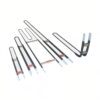
Consider an independent furnace zone designed for a heating capacity of Pzone = 24 kW at 1600°C, utilizing six identical U-shaped Grade 1800 MoSi2 elements (φ 6/12 mm, hot zone length Le = 300 mm) wired in a single series string:
- Determine Hot and Cold Resistance per Element: From manufacturer resistance curves, each element at 1600°C has an operating hot resistance of Rsingle_hot = 0.11 Ω, and a nominal cold resistance at 20°C of Rsingle_cold = 0.01 Ω (an 11:1 ratio).
- Calculate Total Circuit Resistance:
- Total circuit hot resistance: Rtotal_hot = 6 × 0.11 Ω = 0.66 Ω
- Total circuit cold resistance: Rtotal_cold = 6 × 0.01 Ω = 0.06 Ω
- Calculate Rated Operating Voltage and Current:
- Operating voltage: Vhot = √(Pzone × Rtotal_hot) = √(24000 × 0.66) ≈ 125.9 V
- Operating current: Ihot = Pzone / Vhot = 24000 / 125.9 ≈ 190.6 A
- Evaluate Unclamped Cold Inrush Risk: If the full 125.9 V were applied directly to the cold circuit, the instantaneous inrush current would reach:
Iunlimited_cold = 125.9 V / 0.06 Ω ≈ 2,098.3 A (≈ 11 × I_hot)
Consequently, the power system must use an SCR controller to throttle the initial RMS voltage down to a low value (typically 10–15 V during initial firing), clamping the startup current to safe limits.
3.SCR Controller for MoSi₂: Phase-Angle Firing, Current Limiting, and Feedback
Standard on/off temperature controllers and basic solid-state relays cannot safely drive MoSi2 elements. An industrial SCR controller for MoSi2 must incorporate the following control features:
| Control Feature | Operating Principle & Requirement | System Protection Function |
| Phase-Angle Firing | Modulates the conduction angle within each AC half-cycle to continuously regulate RMS load voltage | Essential for cold startup; prevents full AC sine peaks from striking cold, low-resistance elements |
| Fast Electronic Current Limiting | Hardware-interrupt feedback loop that clamps the phase angle instantly if current exceeds a preset limit | Protects elements, fuses, and transformers; threshold is typically coordinated between element limits and breaker ratings |
| Soft-Start Ramp | Gradually opens the conduction angle from 0° over a configurable time ramp | Gives elements time to heat up and build electrical resistance, preventing line voltage sags |
| True RMS / Constant Power Feedback | True RMS sampling of load voltage and current to regulate power (P = V × I) or voltage squared (V2) | Eliminates line voltage fluctuation effects; smoothly increases delivered voltage as elements heat up |
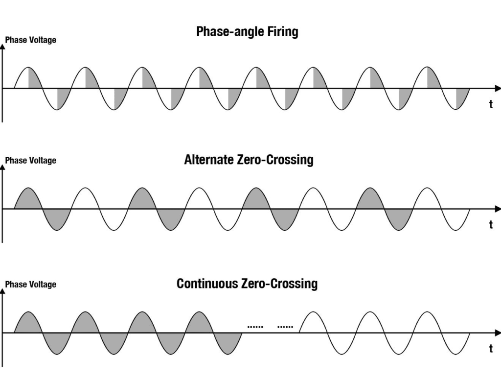
Technical Note on Zero-Cross (Burst Firing) Control:
Conventional zero-cross control applies full line voltage during active cycles, which creates a near dead-short on a cold MoSi2 bank. However, advanced digital power controllers feature a Smart Dual/Hybrid Mode: the system starts in phase-angle mode to clamp current during startup, and once the furnace passes 800°C–1000°C and resistance is established, it switches seamlessly to zero-cross firing to eliminate line harmonics and maximize power factor.
4.Transformer Sizing and Series vs. Parallel Wiring
Because MoSi2 heating loops operate at low voltages and high currents, direct connection to standard 380V, 415V, or 480V line power is impractical. A dedicated dry-type step-down isolation transformer is required.
Transformer kVA and Secondary Tap Selection
- Secondary Voltage Rating: Sized to match the calculated operating voltage Vhot plus a 5% to 10% voltage reserve to compensate for cable drops and supply fluctuations. Unlike SiC transformers—which require wide multi-tap voltage reserves of 1.5× to 2.0× to accommodate long-term element aging (see SiC vs. MoSi2 Heating Elements: Temperature, Atmosphere & Selection)—MoSi2 resistance remains stable over its service life, requiring only minimal taps for process adjustments.
- Apparent Power Rating (kVA): Transformer kVA sizing must account for the lower power factor (PF < 0.7) and harmonic heating generated during phase-angle operation:
Stransformer (kVA) ≥ Pload (kW) / Power Factor × 1.15–1.25
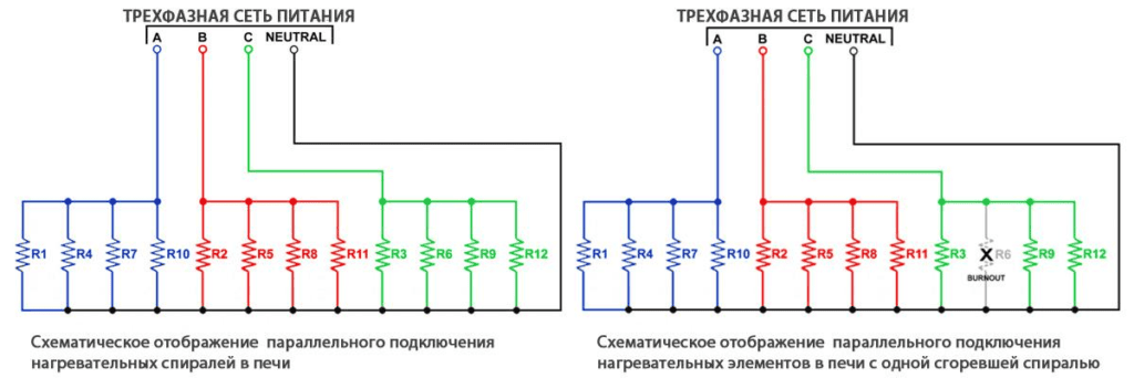
Wiring Topologies: Series vs. Parallel
Design Recommendation: Series strings are strongly preferred whenever roof layout permits. Series wiring raises overall loop resistance, dropping operating current from thousands of amperes down to manageable levels (100A–200A), which significantly lowers busbar and cabling costs. Furthermore, because MoSi2 does not experience resistance aging, replacing a single broken rod in a series circuit does not cause the severe overvoltage burnout typical of aged SiC strings.
5.MoSi₂ Heating Element Startup and Commissioning Procedure
Follow this six-step commissioning sequence to prevent element damage and trip events during initial furnace startup:
- Cold Isolation Verification: Disconnect power and verify insulation resistance between elements and the grounded furnace steel casing using an insulation tester configured to appropriate site voltage standards. Ensure ceramic fiber insulation is dry and passage bricks are free of conductive dust.
- Verify Current Transformers (CT) and True RMS Feedback: Confirm CT ratios, polarities, and scaling parameters in the controller. Ensure secondary-mounted CTs will not saturate under peak start currents.
- Set Initial Safe Current Limits: For initial dry-run testing, set the SCR current limit conservatively below normal full-load current (e.g., 70%–80% × I_hot) to confirm control loop stability.
- Initiate Soft-Start Ramp: Enable the controller and observe the output waveform. Confirm that the conduction angle opens smoothly from 0° and that load current remains clamped within safe thresholds.
- Transition Past the Pesting Band: Once elements establish baseline heat, adjust the current limit to its operational design threshold. Maintain a steady ramp rate through the 400°C–700°C range where low-temperature intergranular oxidation (pesting) occurs.
- Glaze Passivation Soak: For brand-new elements on their first heat cycle, hold the furnace at 1200°C–1400°C in clean air for 1 to 2 hours to form a dense, uniform SiO2 protective glass layer.
6.MoSi₂ Power Control Troubleshooting and RFQ Checklist
Electrical Troubleshooting Matrix
| Observed Symptom | Probable Electrical / Mechanical Cause | Corrective Action |
| Main breaker trips instantly upon start command | SCR fired in zero-cross mode; soft-start ramp set to zero; current-limit board uncalibrated | Switch SCR to phase-angle firing; increase soft-start ramp time; verify CT feedback wiring |
| SCR at 100% command, but furnace temperature stalls | Current limit set too low; transformer secondary voltage tap too low to deliver power at high resistance | Measure true RMS hot voltage and current; raise current limit if within safe limits; step up transformer tap |
| Parallel element shanks vibrate or hum loudly | High instantaneous current spikes during phase-angle firing; loose mechanical clamping | Adjust soft-start ramp to lower inrush rate; verify that double-shank ceramic holder clamps are securely anchored |
Engineering RFQ Specification Checklist
When requesting power supply design assistance or replacement elements from Hongtai Heater Factory, compile the following electrical dataset:
- Element Specifications: Grade (1700 or 1800), shape (U, W, or L), and dimensions (D1/D2 × Le × Lu × A).
- Thermal Loading: Zone power rating (kW), target operating temperature (°C), and required ramp rate.
- Supply Mains: Primary line voltage (e.g., 380V, 415V, 480V, 3-phase/1-phase, 50/60Hz).
- Existing Power Equipment (For Retrofits): Step-down transformer kVA rating and secondary tap voltages, SCR controller model and amp rating, and CT ratio.
Partner with Hongtai for Engineered High-Temperature Furnace Heating Solutions
Achieving stable thermal ramps to 1750°C without nuisance overcurrent trips requires synchronizing element metallurgy with phase-angle SCR control and precision step-down transformers. Hongtai Heater Factory manufactures custom industrial molybdenum disilicide heating elements ((Grade 1700 and Grade 1800) alongside matched terminal braids, holder blocks, and engineering specifications for step-down transformers and SCR integration.
- Consult our Engineers: Send your wiring schematics to the Hongtai Heater Factory technical team for a free design review.
- Visit Us:: www.hongtai-heater.com