Nickel-chromium resistance alloys dominate electric heating applications up to 1200°C due to their exceptional hot-tensile strength, cyclic fatigue endurance, and room-temperature ductility. However, choosing the right nichrome wire grades requires balancing alloy chemistry—specifically nickel, chromium, and iron ratios—against operating temperature, atmosphere compatibility, and resistance stability.
This guide helps element manufacturers and procurement engineers select the optimal nichrome heating wire grade to prevent premature burnout. If you are comparing nickel alloys against FeCrAl or ceramics, see our baseline guide: Industrial Furnace Heating Elements: NiCr vs. SiC vs. MoSi2.
1.Comparing Standard Nichrome Wire Grades
Commercial NiCr resistance wire manufactured to international specifications (such as ASTM B344 and DIN 17470) is categorized into four primary engineering alloy grades:
| Alloy Grade | Nominal Composition (wt%) | Max Continuous Element Temp | Resistivity (20°C, microhm-m) | Magnetic & Mechanical Profile | Primary Industrial Applications |
| NiCr 80/20 (Nikrothal 80 / Cr20Ni80) | approx. 80% Ni, 20% Cr | 1200°C | approx. 1.09 | Completely non-magnetic; highest hot-creep resistance; minimal thermal sag | The industrial standard for heavy-duty electric kilns and high-reliability heating elements. Specified for high-temperature laboratory furnaces, sintering ovens, and long-life tubular heating elements. |
| NiCr 70/30 (Nikrothal 70 / Cr30Ni70) | approx. 70% Ni, 30% Cr | 1250°C | approx. 1.18 | Non-magnetic; exceptional resistance to “green rot” and alternating redox atmospheres | Engineered for carburizing, reducing, and controlled-atmosphere furnaces. Offers the highest temperature ceiling among commercial Ni-Cr alloys. |
| NiCr 60/15 (Nikrothal 60 / Cr15Ni60) | approx. 60% Ni, 15% Cr, Bal. Fe | 1150°C | approx. 1.12 | Slightly magnetic (increases with cold drawing); high cold-tensile yield strength | Cost-effective general-purpose grade. Widely utilized in commercial food equipment, open-coil HVAC duct heaters (see Engineering Duct Heater Banks), and domestic water immersion heaters. |
| NiCr 30/20 (Nikrothal 30 / Cr20Ni35) | approx. 30%–35% Ni, 20% Cr, Bal. Fe | 1050°C | approx. 1.04 | Definite ferromagnetic response; lower hot-yield strength | Economical low-temperature resistance alloy designed for continuous drying ovens, space heaters, and light-duty ceramic core heating coils. |
2.High-Temperature Oxidation: Why NiCr 80/20 Outlasts Alternate Alloys
The operational service life of NiCr 80/20 heating wire depends on its ability to form and maintain an adherent, self-healing oxide glaze when energized in oxidizing environments.
- Chromium Oxide (Cr2O3) Scale Integrity: Above 800°C, chromium selectively diffuses to the wire surface to form a continuous, thermodynamically stable chromia (Cr2O3) layer. This green oxide scale acts as an electrical insulator and prevents deeper oxygen penetration into the core alloy.
- Superior Thermal Spalling Resistance: Iron-chromium-aluminum (FeCrAl) alloys form an alumina (Al2O3) scale that is mechanically rigid and prone to micro-cracking and flaking during rapid thermal cycling. In contrast, the Cr2O3 scale on nichrome heating wire closely matches the thermal expansion coefficient of the parent austenitic matrix. Under frequent on/off power cycling, the chromia scale flexes without spalling, preventing rapid chromium depletion.
- Iron Contamination Trade-Off: In iron-bearing grades like NiCr 60/15 and NiCr 30/20, high-temperature operation produces mixed iron oxides (FeO / Fe2O3). Iron oxides are porous and have lower melting thresholds, which accelerates scale breakdown and internal oxidation above 1100°C.
3.Resistivity Stability & Temperature Correction Factors (Ct)
Designing electric heating elements for precise wattage output (P = V2 / R) requires adjusting the baseline 20°C cold resistance (R20) using the temperature correction factor (Ct):
Rhot = R20 × Ct
Temperature Correction Factor (Ct) Across Operating Temperatures
| Operating Temperature | NiCr 80/20 (Ct) | NiCr 70/30 (Ct) | NiCr 60/15 (Ct) | NiCr 30/20 (Ct) |
| 20°C | 1.000 | 1.000 | 1.000 | 1.000 |
| 400°C | 1.025 | 1.015 | 1.045 | 1.080 |
| 600°C | 1.045 | 1.028 | 1.075 | 1.135 |
| 800°C | 1.065 | 1.040 | 1.110 | 1.190 |
| 1000°C | 1.075 | 1.055 | 1.140 | 1.240 |
| 1200°C | 1.080 | 1.065 | — | — |
Engineering Implications:
- Linear Power Output Without Inrush Surges: From room temperature up to 1200°C, the electrical resistance of NiCr 80/20 increases by only 8%. Because its resistance curve is essentially flat compared to molybdenum disilicide (which shifts by a factor of 10× to 14×, as detailed in MoSi2 Heating Element Power Control: Cold Resistance, Startup Current & SCRs), standard nichrome circuits draw almost zero startup inrush current.
- Simplified Solid-State Switching: This predictable resistance characteristic allows systems to be driven directly across line voltage via standard solid-state relays (SSRs) or mechanical contactors, eliminating the need for expensive phase-angle SCR controllers or variable step-down transformers.
4.Atmospheric Compatibility & Preventing “Green Rot”
Operating atmosphere directly affects the lifespan of NiCr resistance wire. Incorrect pairing of material grade and atmosphere can trigger rapid structural degradation.
Preventing Preferential Internal Oxidation (“Green Rot”)
- Mechanism: When NiCr 80/20 runs in marginally oxidizing or oxygen-depleted atmospheres (such as cracked ammonia, moist hydrogen, or endothermic gas) within the critical temperature band of 800°C to 1050°C, the partial pressure of oxygen is too low to form a continuous surface Cr2O3 scale. Oxygen diffuses internally along grain boundaries, precipitating isolated chromium oxide particles while leaving a porous, unalloyed nickel matrix.
- Visual Symptoms: The wire develops a dusty, olive-green surface appearance (“green rot”). The element becomes brittle at ambient temperatures, its resistance climbs erratically, and it fractures under minimal mechanical vibration.
- Mitigation Strategy: In protective, carburizing, or low-dew-point atmospheres, specify NiCr 70/30. Its higher chromium content (30%) promotes continuous scale formation even at depressed oxygen partial pressures.
Critical Warning — Sulfur Contamination: Never expose nickel-chromium alloys to sulfurous atmospheres. Above 645°C, trace sulfur reacts rapidly with nickel to form a nickel sulfide (Ni3S2) eutectic network along grain boundaries. This eutectic melts at 645°C, causing the wire to liquefy and snap within hours. In sulfur-bearing kilns, iron-chromium-aluminum (FeCrAl) alloys must be used instead.
5.Mechanical Ductility & High-Temperature Creep Resistance
When evaluating nichrome against alternative metallic resistance alloys, nichrome heating wire offers distinct mechanical and manufacturing advantages:
- No High-Temperature Embrittlement: FeCrAl alloys undergo rapid grain coarsening above 950°C, causing severe ambient embrittlement. Once fired, an FeCrAl element cannot be uncoiled, bent, or adjusted without snapping. Nichrome alloys feature a face-centered cubic (FCC) austenitic microstructure that retains high ductility after thousands of thermal hours. Elements can be safely removed, serviced, or re-stretched during maintenance.
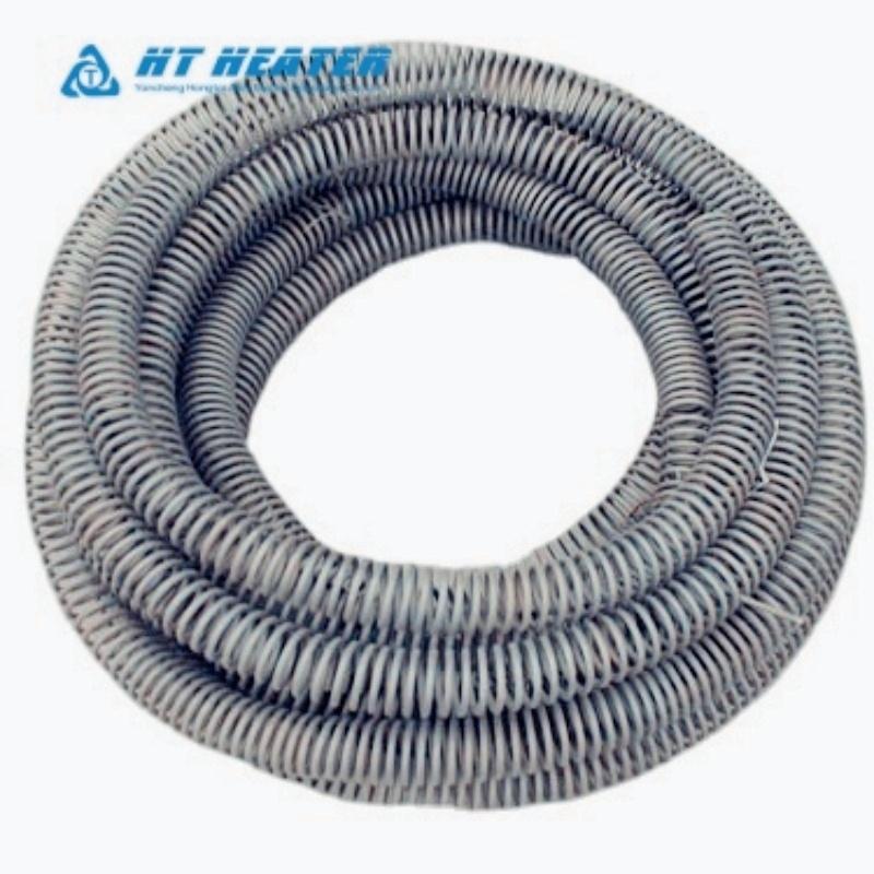
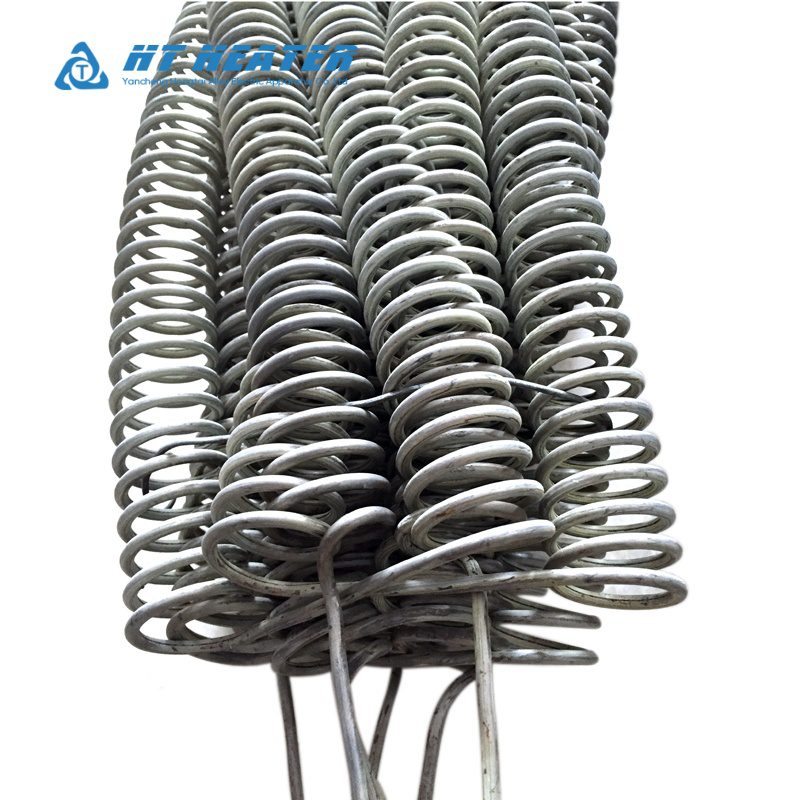
- Creep and Sag Resistance: In the 1000°C to 1150°C range, NiCr 80/20 exhibits significantly higher hot-tensile strength and creep resistance than ferritic alloys. When formed into open spiral coils and mounted horizontally across ceramic support tubes (as seen in Ceramic Bobbin Heaters: Construction, Resistance Wire & Applications), nichrome maintains its pitch spacing without sagging, preventing adjacent coils from shorting.
6. Procurement Specification Checklist for Element Manufacturers
To ensure consistent coil resistance and trouble-free automated winding from Hongtai Heater Factory, specify the following parameters in your RFQ:
NICHROME RESISTANCE WIRE RFQ SPECIFICATION BLOCK
- Alloy Grade : NiCr 80/20 (UNS N06003) / NiCr 70/30 / NiCr 60/15 / NiCr 30/20
- Profile & Size :
- Round Wire : Diameter Ø [mm / AWG] (Dimensional tolerance: ±0.01 mm)
- Flat Ribbon : Thickness [mm] × Width [mm]
- Annealing State : Bright Annealed (Soft) / Surface Oxidized
- Electrical Limits : Target Resistance [Ω/m at 20°C] with tolerance (Standard ±5%, Precision ±3%)
- Spool / Packaging : DIN 125 / DIN 160 / DIN 200 / Coilless Pail Pack (for automatic coilers)
- Target Application: Swaged Tubular Heaters / Open Coil Suspensions / Ceramic Core Windings
Partner with Hongtai for Precision Resistance Wire & Heating Solutions
Consistent thermal performance requires precise alloy chemistry, uniform grain sizing, and tightly controlled cold-drawn surface finishes.Hongtai Heater Factory manufactures a comprehensive range of industrial nichrome heating wire, precision resistance ribbons, and pre-formed corrugated heating elements. Every production batch is bright-annealed, resistance-tested, and spooled to deliver reliable winding performance for global heating element manufacturers and industrial kiln builders.
- Consult our Engineers: Send your wiring schematics to the Hongtai Heater Factory technical team for a free design review.
- Visit Us:: www.hongtai-heater.com