Sizing Cartridge Heaters for an aluminum injection or compression mold is a transient heat-balance problem—not a surface watt density guessing game. Because aluminum alloys conduct heat roughly three to four times faster than tool steel, an aluminum mold distributes heat quickly, yet it also loses heat rapidly into press platens and surrounding air if not properly insulated.
An accurate cartridge heater power calculation for Aluminum Molds starts by calculating the sensible heat required to raise the mold assembly within your target mold heat up time, adding conductive and convective losses, and verifying that the chosen heater layout maintains safe bore fit and sheath watt density.
1. Material Factors in Aluminum Mold Heating Calculations
Three physical characteristics of aluminum directly shape your aluminum mold heating calculation:
- High Specific Heat Capacity: Aluminum absorbs roughly 0.90 kJ/(kg·K)—nearly double that of tool steel (≈ 0.46 kJ/(kg·K)). Per kilogram, aluminum requires almost twice the energy per degree of temperature rise.
- High Thermal Conductivity (160–205 W/(m·K)): Heat spreads rapidly from the bore into the cavity face, helping smooth out temperature gradients when heater spacing is matched to mold thickness and cavity geometry.
- Differential Thermal Expansion & Alloy Temper: Aluminum expands roughly twice as fast as stainless steel or Incoloy heater sheaths (≈ 23 × 10-6 K-1 vs. ≈ 11–16 × 10-6 K-1). As the mold heats up, the bore expands slightly more than the heater, increasing the running air gap. Additionally, for heat-treated alloys like 6061-T6, verify with your tooling metallurgist that continuous exposure at 185°C or higher will not cause unacceptable over-aging or mechanical softening under clamping loads.
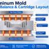
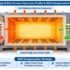
2. Mold Heat-Load Schematic & Governing Equations
To size total installed kW, separate transient warm-up energy from steady-state holding losses:
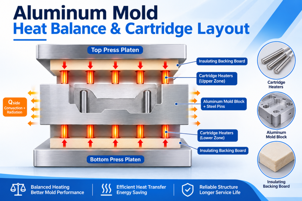
Core Sizing Formulas
- Composite Sensible Heat Power (Pabs): Sum the heat absorbed by both the aluminum block and any steel inserts, pins, or backing plates: Pabs = [(mAl × cpAl + msteel × cpsteel) × (Ttarget – Tinitial)] / t
- t = Target heat-up time in seconds (minutes × 60)
- Average Ramp-Up Heat Losses (Ploss,avg): Calculate conductive losses through platen insulation boards (Pplaten = Uins × Aplaten × ΔTavg) plus convective/radiative losses from exposed perimeter faces (Pside = hcomb × Aside × ΔTavg), using the midpoint temperature rise ΔTavg = [(Ttarget + Tinitial) / 2] – Tambient.
- Preliminary Installed Power (Ptotal): Ptotal = (Pabs + Ploss,avg) × SF
- SF = Safety factor (typically 1.15 to 1.25) to cover voltage variations, shop drafts, and controller cycling.
3. Worked Engineering Example: 6061 Aluminum Mold Sizing
Design Target: Heat a 6061 aluminum mold half from 25°C ambient to 185°C within a target 20-minute heat-up window on a 240V supply.
Input Data
- Mold Dimensions: 400 mm × 300 mm × 150 mm (0.018 m³)
- Composite Mass: 48.6 kg aluminum (cp = 0.90 kJ/(kg·K)) + 4.0 kg steel guide pins/inserts (cp = 0.46 kJ/(kg·K))
- Temperature Rise (ΔT): 185°C – 25°C = 160 K (ΔTavg = 80 K)
- Target Heat-Up Time (t): 20 min = 1,200 s
- Platen Insulation: 10 mm fiberglass-reinforced thermal boards (Uins ≈ 15 W/(m²·K))
Step 1: Sensible Heat Power (Pabs)
Eabs = [(48.6 × 0.90) + (4.0 × 0.46)] × 160 = (43.74 + 1.84) × 160 = 7,293 kJ
Pabs = 7,293 kJ / 1,200 s = 6.08 kW
Step 2: Average Ramp-Up Losses (Ploss,avg)
- Platen Faces (Aplaten = 0.24 m²): 15 × 0.24 × 80 = 288 W
- Exposed Perimeter (Aside = 0.21 m², h_comb ≈ 14 W/(m²·K)): 14 × 0.21 × 80 = 235 W
- Total Average Ramp Loss: 288 W + 235 W = 0.52 kW (Steady-state holding loss at 185°C is roughly 1.05 kW).
Step 3: Preliminary Installed Wattage (Ptotal)
Ptotal = (6.08 kW + 0.52 kW) × 1.20 = 7.92 kW → 8.0 kW (Preliminary Selection)(Note: 8.0 kW serves as the baseline installed rating; actual ramp time depends on PID tuning, line voltage stability, and press heat-sink contact, and should be verified during mold commissioning).
Step 4: Heater Selection & Preliminary Watt Density Check
Select 8 swaged High-Density Cartridge Heaters rated at 1,000 W each (240V) drilled across the 300 mm width:
- Dimensions: 12.7 mm (0.500″) nominal diameter (actual OD 12.60 mm); 280 mm overall length with 240 mm (24.0 cm) active heated length (20 mm unheated ends).
- Active Sheath Area: Asheath = π × 1.26 cm × 24.0 cm = 95.0 cm²
- Calculated Watt Density: Watt Density = 1,000 W / 95.0 cm² = 10.5 W/cm² (67.7 W/in²)
This 10.5 W/cm² figure serves as a favorable preliminary screening value. Final suitability depends on internal MgO compaction quality, exact bore clearance at 185°C, and the heater manufacturer’s maximum sheath temperature curve—see our Cartridge Heater Watt Density Calculation guide for detailed sheath loading limits.
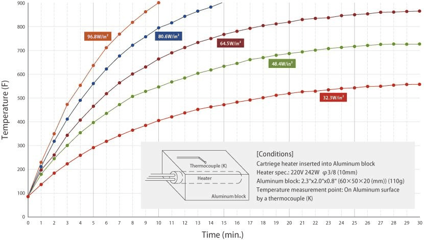
4. Layout, Bore Fit & Installation Verification
Even an accurate kW calculation will fail if heat cannot transfer efficiently across the bore interface or if zones are poorly balanced:
- Zone Power Distribution: Mold edges and platen-adjacent regions lose heat faster than the mold core. Rather than spacing all heaters identically, place heaters slightly closer near high-loss perimeter zones—or use distributed-wattage winding—to maintain uniform cavity face temperatures.
- Bore Fit & Thermal Expansion Clearance: Ream holes cleanly to match the heater manufacturer’s recommended bore tolerance for your specific diameter and operating temperature (accounting for aluminum’s greater thermal expansion). Apply only a thin, manufacturer-approved high-temperature thermal interface / anti-seize compound to prevent galling without insulating the sheath. Follow proper Cartridge Heater Installation & Removal Guide practices to avoid bore scoring.
- Active Length & Lead Exit Clearance: Keep active heated sections recessed inside the aluminum block so lead exits do not overheat. Where press tie-bars or side plates restrict wire bending radius, specify Right-Angle Cartridge Heaters or internally swaged flexible leads so the heated section remains fully seated in the bore.
- Thermocouple Positioning: Place the control thermocouple midway between adjacent heaters and close to the molding cavity face to prevent premature controller cycling or thermal overshoot.
Partner with Hongtai for Custom Aluminum Mold Cartridge Heaters
Reliable mold heating requires pairing accurate thermal load calculations with tight-tolerance, high-compaction cartridge heaters. Hongtai Heater Factory manufactures custom swaged cartridge heaters engineered for aluminum and steel tooling—featuring centerless-ground ODs for precision reamed bores, distributed wattage profiles for edge-loss compensation, and rugged right-angle or stainless-braided lead exits.
- Consult our Engineers: Send your wiring schematics to the Hongtai Heater Factory technical team for a free design review.
- Visit Us:: www.hongtai-heater.com