When a high-temperature kiln stalls at 1220°C despite the power controller running at 100% output, the primary suspect is silicon carbide heater aging. Unlike metallic elements that maintain flat resistance, SiC heating element resistance increases progressively over operating hours.
However, low furnace output does not always mean dead elements. Active SCR current limits, insufficient transformer tap voltage, or mismatched series wiring often mimic element burnout. This guide provides electrical engineers and maintenance supervisors with a practical framework to calculate power loss, configure SiC heater power control, and execute cost-effective replacements. If you are comparing element materials at the initial kiln design stage, refer to our baseline guide on Industrial Furnace Heating Elements: NiCr vs. SiC vs. MoSi₂.
1. Why SiC Elements Age & The Non-Linear TCR Curve
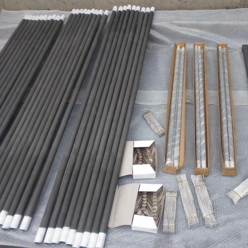
A gradual SiC element resistance increase is driven by slow high-temperature oxidation. As silicon carbide reacts with oxygen to form a protective silica (SiO2) glaze, internal micropores oxidize and narrow the effective conductive path. Aging accelerates under high surface watt density, water vapor or reducing atmospheres, and frequent batch thermal cycling.
Furthermore, SiC exhibits a strongly non-linear temperature coefficient of resistance (TCR). Resistance drops as the rod heats up from room temperature (NTC), reaches a valley (typically between 600°C and 800°C, depending on crystal grade), and then rises steadily at high operating temperatures (PTC).
| Resistance State | Test Condition | Engineering Application & Limits |
|---|---|---|
| Cold Resistance | Room temp (20°C) with a multimeter | Continuity check only. Never use cold ohm readings to calculate wattage or match series sets. |
| Calibrated Hot Resistance (R₀) | Factory-tested at calibration temp (e.g., 1000°C–1050°C) | Stamped on the cold end (e.g., 2.0 Ω). Mandatory baseline for voltage sizing and series matching. |
| Aged Hot Resistance (Raged) | Live operating calculation (R = V / I) | Quantifies aging ratio to determine whether to step up transformer taps or replace elements. |
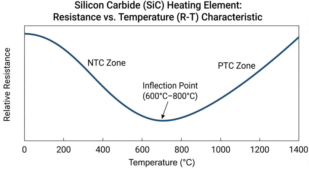
2. How Resistance Aging Reduces Power (Worked Example)
Under a fixed supply voltage (V), thermal power output (P) drops inversely as resistance (R) rises:
P = V2 / R
Consider a SiC zone with an initial hot resistance of R_0 = 2.0 Ω supplied by a fixed 100 V tap:
| Service Stage | Supply Voltage (V) | Hot Resistance (R) | Actual Power (P=V²/R) | Branch Current (I) | Operational Impact |
|---|---|---|---|---|---|
| New (1.0x R₀) | 100 V | 2.0 Ω | 5,000 W (100%) | 50.0 A | Normal ramp rate; SCR runs at 70%–80% output |
| Mid-Life (1.5x R₀) | 100 V | 3.0 Ω | 3,333 W (down 33.3%) | 33.3 A | SCR saturates at 100%; sluggish heat recovery |
| Late-Life (3.0x R₀) | 100 V | 6.0 Ω | 1,667 W (down 66.7%) | 16.7 A | Furnace stalls below setpoint without voltage boost |
The Fix: To restore 5,000 W at 3.0 Ω, supply voltage must increase to V = √(5000 × 3.0) ≈ 122.5 V.
3. SiC Heater Power Control: Transformers & SCR Modes
An engineered SiC heater power control panel must limit high current when elements are new (or passing through the TCR valley) while providing voltage headroom as elements age:
- Multi-Tap Transformers: Provide stepped secondary voltage taps. While 1.4x to 2.0x initial voltage is a common preliminary benchmark, exact headroom must be sized using the manufacturer’s target end-of-life resistance (V_max ≥ √(P_rated × R_max)).
- Phase-Angle SCR Firing: Smoothly regulates RMS voltage within each AC half-cycle. Enables soft-start ramps and active current limiting.
- Zero-Cross (Burst) SCR Firing: Switches complete AC sine cycles to maximize power factor and eliminate harmonics, but cannot limit peak instantaneous current within an active cycle.
- Constant-Power Feedback (P = V × I): Automatically widens SCR conduction as R increases to hold wattage steady. Note: An SCR cannot boost voltage above the active transformer tap.
For a direct comparison of how SiC power control differs from the extreme cold-inrush protection required for MoSi2 elements, read SiC vs. MoSi2 Heating Elements: Temperature, Atmosphere & Selection.
4. 5-Step Field Diagnostic & Troubleshooting Guide
Before ordering replacement rods for an underperforming furnace, execute this diagnostic protocol:
- Check Thermal Leaks: Inspect door seals, fiber insulation, and purge gas rates for abnormal heat loss.
- Verify SCR Status: Confirm whether an active Current Limit clamp or blown fuse is throttling voltage despite a 100% PID demand.
- Measure Live True-RMS V and I: Have a qualified electrician measure load voltage and current at operating temperature.
- Calculate Live Resistance (Ractual = V / I): Compare live resistance against the initial cold-end stamp (R0).
- Step Up Tap or Replace: If Ractual is 1.3x–2.0x R0 and higher transformer taps are available, step up the voltage tap. If the transformer is on its maximum tap and resistance has reached the manufacturer’s end-of-life limit (often 3x–4x R0), schedule replacement.
| Field Symptom | Root Engineering Cause | Corrective Action |
|---|---|---|
| SCR at 100%, low amps, temperature stalls | Normal resistance aging exceeds active voltage tap capacity | Step up transformer secondary tap; replace bank if on max tap |
| Breaker trips immediately after installing new rods | Transformer left on high “aged” voltage tap | Reset transformer to initial low-voltage tap; verify SCR current limit |
| One rod in a group glows white-hot and snaps | Series resistance mismatch (or mixing new and old rods) | Match series rods within ±5% (or ±0.1–0.2 Ω) of stamped R₀ |
| Arcing or melted aluminum at cold ends | Loose C-clamps, oxidized braids, or conductive grease | Replace spring clips and aluminum braids; keep terminals clean and dry |
5. Series vs. Parallel Wiring & Replacement Rules
- The Series Runaway Risk: Because current I is identical across a series string (Pi = I2 Ri), wiring a new 2.0 Ω rod in series with an aged 4.0 Ω rod forces the aged rod to absorb double the wattage, causing rapid thermal runaway and fracture.
- The Smart Rotation Strategy: Never mix a single new rod into an aged series string. Instead, replace the entire series branch with a matched set of new rods. Save, test, and tag the intact aged rods removed from that circuit to use as matched spares for other aged branches later.
6. SiC Replacement RFQ Checklist
When requesting replacement silicon carbide heating elements from Hongtai Heater Factory, provide these six specs (for detailed geometry guidelines, consult Silicon Carbide Heating Elements: Types, Shapes & Selection Guide):
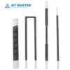
- Profile Code: ED Straight, DB Dumbbell, U-Type, W-Type, or SG/SGR Spiral.
- Dimensions (mm): Outer Diameter (OD), Hot Zone (HZ), Cold End (CZ), Overall Length (OL), and leg spacing (A).
- Electrical Specs: Rated wattage (W), initial voltage (V), and stamped calibrated resistance (Ω).
- Circuit Topology: Series × parallel arrangement, transformer voltage tap range, and SCR rating.
- Furnace Conditions: Chamber temperature (°C), atmosphere composition, and mounting orientation.
- Hardware: Aluminum braid length and stainless steel spring clamp type.
Partner with Hongtai for Engineered High-Temperature Furnace Heating Solutions
Achieving uniform high-temperature radiant heating and extended kiln campaign life requires mastering refractory ceramic physics, surface watt density limits, and resistance-matched electrical zoning.Hongtai Heater Factory manufactures custom industrial silicon carbide (SiC) and molybdenum disilicide (MoSi2) heating elements engineered precisely to your hot zone dimensions, resistance tolerances, and furnace atmosphere specifications..
- Consult our Engineers: Send your wiring schematics to the Hongtai Heater Factory technical team for a free design review.
- Visit Us:: www.hongtai-heater.com