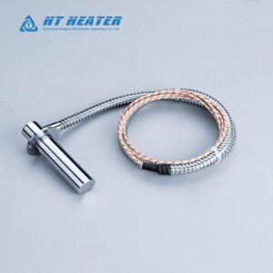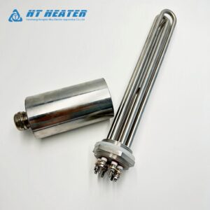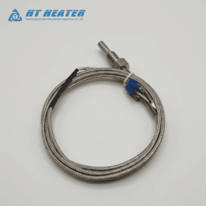
thermocouple for ceramic heater selection dictates the ultimate precision of your thermal loop and directly impacts product yield in automated thermoforming, curing, and drying lines. For automation engineers configuring closed-loop PID control systems, choosing between a Type J and Type K sensor—or improperly positioning the sensing junction—frequently leads to temperature hunting, overshoot, and scrap losses.
Selecting the wrong sensor calibration or misunderstanding the thermal response lag inside a refractory matrix will corrupt your control loop feedforward mathematics. This technical guide evaluates sensor physics, PID loop behavior, and wiring SOPs to help you select the ideal sensor configuration for your machine builds.
1. Type J vs Type K Thermocouple for Ceramic Heater Integration
Understanding the thermoelectric alloys and operational constraints of a type j vs type k thermocouple is the first step in thermal system integration. Thermocouples generate a temperature-dependent electromotive force (EMF) via the Seebeck effect:
Where S(T) represents the temperature-dependent Seebeck coefficient of the specific metal pair according to IEC 60584-1 international thermocouple standards.
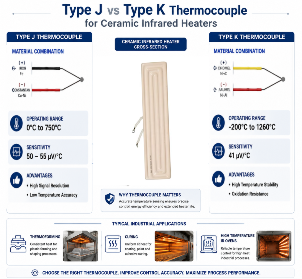
| Parameter / Feature | Type J Thermocouple (Iron / Constantan) | Type K Thermocouple (Chromel / Alumel) |
| Operating Range | 0°C to 750°C (32°F to 1382°F) | -200°C to 1260°C (-328°F to 2300°F) |
| Seebeck Sensitivity | ~50 µV/°C to 55 µV/°C (Higher Signal Resolution) | ~41 µV/°C (Standard Industrial Signal) |
| Environmental Tolerance | Susceptible to iron leg oxidation in moist environments | Excellent oxidation resistance at elevated temperatures |
| Primary Application | Plastics machinery, low-temp IR curing | High-temperature IR ovens, general industrial heating |
For standard medium-wave ceramic emitters operating under 700°C, a Type J sensor offers a higher voltage output per degree Celsius, providing finer signal resolution for PLC analog input cards. However, for high-wattage arrays requiring rapid ramp rates, Type K remains the global industry standard due to its superior immunity to high-temperature conductor oxidation.
2. Thermocouple for Ceramic Heater Location: Impact on PID Closed-Loop Control
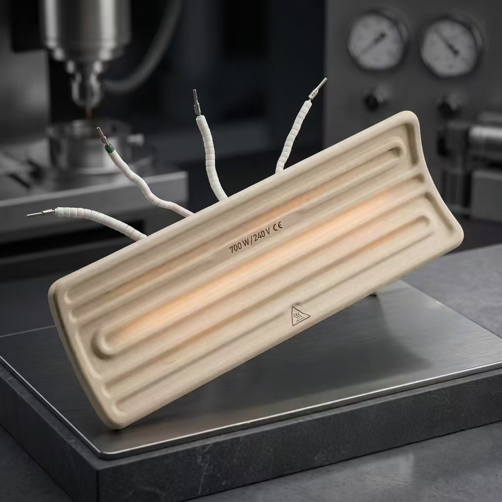
When specifying a built-in thermocouple heater, the physical location of the measuring junction relative to the internal resistance wire creates a fundamental trade-off between element protection and process temperature accuracy.
Option A: Internal Embedded Junction (Cast Into Refractory Body)
In a built-in thermocouple heater, the junction is embedded directly within the ceramic clay, directly adjacent to the nickel-chrome heating coil.
- PID Loop Dynamics: The sensor detects wire temperature almost instantly. This rapid feedback loop allows the PID controller to clip power spikes before the wire exceeds its melting threshold.
- Process Lag: Because ceramic possesses thermal mass, there is a distinct thermal resistance phase lag between the internal wire temperature and the actual infrared radiant energy reaching the target material.
If your PID controller is hunting or overshooting due to improper loop tuning, consult our technical breakdown on Troubleshooting Premature Failure in Ceramic Infrared Heating Elements: A Diagnostic Guide to diagnose thermal loop instability.
Option B: External Surface Contact Sensor
Attaching a spring-loaded or bayonet-style thermocouple directly to the face or back reflector of the heater measures localized thermal output rather than coil temperature. This improves process consistency for sensitive polymer sheets but leaves the internal resistance wire vulnerable to burnout if power limits are miscalculated. Ensure your baseline wattages are within safe limits by reviewing How to Calculate Watt Density for Ceramic Infrared Heaters.
3. Engineering Selection Matrix for Built-In Thermocouple Heater Systems
To maintain high product yields in automated manufacturing, automation engineers can select sensor configurations using this application matrix:
| Operating Condition | Recommended Sensor Type | Recommended Junction Position | Primary Control Benefit |
| Thermoforming / Vacuum Forming | Type K | Built-In (Embedded) | Prevents element burnout during rapid cycle times |
| Precision Paint / Coating Curing | Type J | External Surface Contact | Maximizes target temperature accuracy and yield |
| High-Vibration Machinery | Type K (Grounded) | Built-In (Embedded) | Protects delicate leads from mechanical fracture |
| Multi-Zone Oven Arrays | Type K | Built-In (Integrated) | Simplifies wiring harness design in modular banks |
For comprehensive background data on designing complete modular heating arrays, reference our core technical manual: Ceramic Infrared Heaters: The Complete Engineering & Selection Guide.
4. Field Installation SOP: Thermocouple for Ceramic Heater Wiring
To ensure electromagnetic interference (EMI) does not corrupt your temperature controller signals during operation, follow this installation checklist:
Cold Junction Compensation: Verify that your PLC or temperature controller’s internal reference junction compensation (RJC) is calibrated according to NIST standard reference tables published by the NIST ITS-90 Thermocouple Database.
Polarity & Wire Matching: Always use dedicated Type J or Type K extension wire to connect the heater to the control panel. Never use standard copper hookup wire, as secondary junctions will introduce severe EMF reading errors.
Noise Shielding: Route low-voltage thermocouple signals in a separate conduit isolated from high-voltage 480V/230V AC heater power lines to prevent induced electrical noise on the PID analog input module.