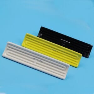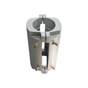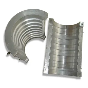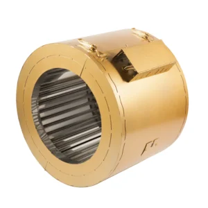
material emissivity infrared heating dynamics govern the fundamental thermodynamics of non-contact thermal processing. For senior R&D engineers and laboratory researchers designing thermoforming, curing, or moisture-evaporation equipment, achieving maximum energetic efficiency requires far more than simply supplying electrical power to a heating element. It demands precise spectral matching between the emitter’s radiation spectrum and the target substrate’s molecular absorption characteristics.
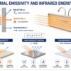
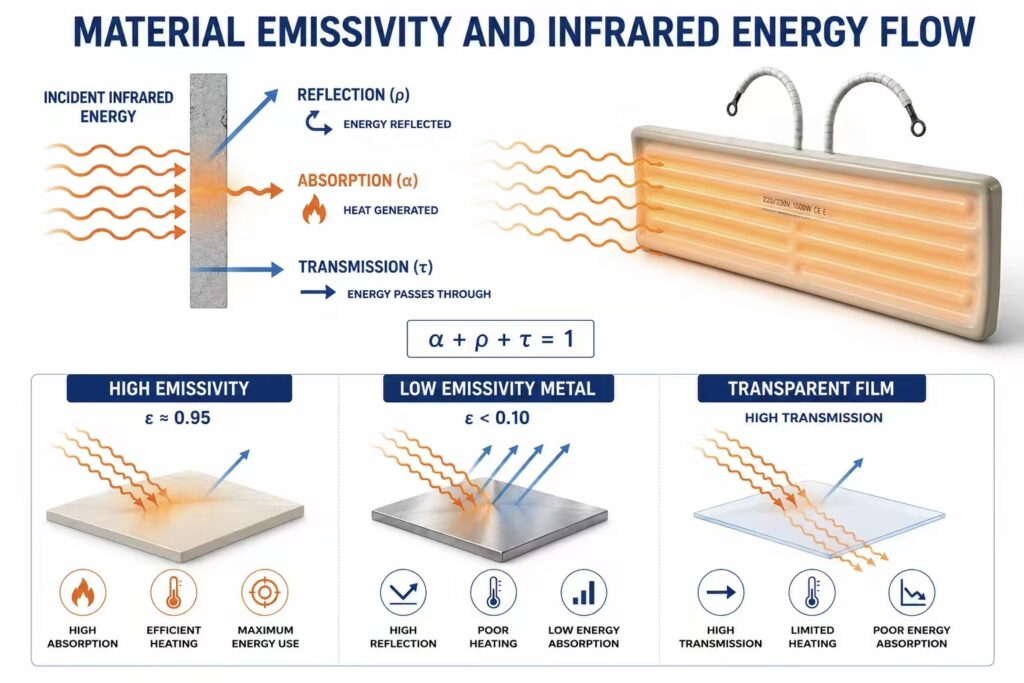
When infrared energy strikes a target surface, the total incident radiant energy is divided into three distinct physical phenomena: absorption, reflection, and transmission. Understanding material emissivity infrared heating interactions is essential to overcoming thermal efficiency barriers in industrial applications.
1. Fundamental Physics: Kirchhoff’s Law and Material Emissivity in Infrared Heating
According to Kirchhoff’s Law of Thermal Radiation, at thermal equilibrium, the spectral emissivity (ελ) of a material equals its spectral absorptivity (αλ). For any real opaque or semi-transparent body, conservation of energy establishes the core equation for material emissivity infrared heating analysis, relating absorptivity (αλ), reflectivity (ρλ), and transmissivity (τλ):
In industrial thermal processing, an ideal target substrate exhibits a high emissivity rating (ε → 1.0) across the specific infrared wavelengths emitted by the heat source.
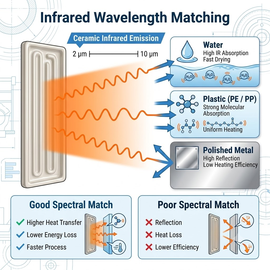
An industrial ceramic matrix operating at 300°C to 700°C emits long-to-medium wave radiation predominantly in the 2 µm to 10 µm spectral band. High ceramic heater radiation efficiency is achieved when this emission profile overlaps directly with the fundamental molecular vibration modes (C-H, O-H, and N-H bond stretching) of organic polymers and water. Research data maintained by the NIST Physical Measurement Laboratory confirms that matching emitter peak emission wavelength to substrate absorption bands increases process energy coupling by up to 40% compared to mismatched broadband sources.
2. Wavelength Matching and IR Absorption Rate Across Target Substrates
The operational ir absorption rate varies significantly across industrial materials depending on chemical bond structures and surface conditions:
- Polymers and Thermoplastics: Materials like polyethylene (PE), polypropylene (PP), and PVC exhibit sharp infrared absorption peaks in the 3.3 µm to 3.5 µm range and again from 6 µm to 10 µm. Shortwave infrared radiation passes right through thin polymer films without heating them (τλ → 1.0), whereas medium-to-long wave ceramic radiation is rapidly absorbed within the surface layers.
- Water and Water-Based Coatings: Water features an extraordinarily high absorption peak at approximately 3.0 µm and between 5.8 µm and 6.2 µm. Medium-wave ceramic emitters operating at approximately 500°C produce peak radiant energy that perfectly matches these O-H bond resonance bands, driving rapid moisture evaporation.
- Metals and Metallic Foils: Unoxidized, polished metals possess very low emissivity (ε < 0.10) and high reflectivity (ρλ > 0.90), reflecting almost all radiant heat back to the emitter.
To evaluate how different physical element geometries influence directional radiant density, engineers can review our comparative study on Hollow vs. Solid Ceramic Heaters: Heat Transfer Efficiency Analysis.
| Target Substrate Material | Emissivity Rating (ε) | Peak IR Absorption Bands (µm) | Optimal Heating Element Match |
| Polyethylene / Polypropylene | 0.90 – 0.95 | 3.4 µm, 6.8 µm – 7.2 µm | Medium-Wave Ceramic Infrared |
| Water / Aqueous Coatings | 0.95 – 0.98 | 2.9 µm, 6.0 µm | Ceramic Refractory Emitter |
| PET / Polycarbonate | 0.85 – 0.92 | 3.1 µm, 5.8 µm – 9.0 µm | Solid Ceramic Emitter Array |
| Polished Aluminum / Copper | 0.03 – 0.07 | N/A (Highly Reflective) | Convective / Direct Contact |
| Anodized / Oxidized Steel | 0.75 – 0.88 | 2.0 µm – 8.0 µm | High-Density IR Ceramic Panel |
When selecting between fast-response quartz emitters and ceramic elements for rapid cycle testing, consult Quartz vs. Ceramic Infrared Heaters: Response Time & Wavelength Comparison to analyze radiant thermal inertia curves.
3. Calculating Radiant Heat Flux and Optimizing Ceramic Heater Radiation Efficiency
To quantify the net radiant power transferred from a ceramic heater radiation array to a target substrate, laboratory researchers utilize the Stefan-Boltzmann radiation transfer model adjusted for gray-body surface interactions:
Where:
- qnet = Net radiant heat flux density (W/m²)
- σ = Stefan-Boltzmann constant (5.6704 × 10⁻⁸ W/m²·K⁴)
- T1 & T2 = Absolute surface temperatures of the emitter and substrate (K)
- ε1 & ε2 = Emissivity ratings of the ceramic emitter (~0.92) and target substrate
- F12 = Geometric view factor between emitter array and product surface
When surface power limits are miscalculated, high surface temperatures can degrade sensitive organic glazes or cause element burnout. Laboratory personnel should verify safe operational wattages using How to Calculate Watt Density for Ceramic Infrared Heaters.
4. Practical Engineering Protocol for Evaluating Material Emissivity in Infrared Heating
To standardize thermal efficiency audits in R&D facilities, engineering teams should execute the following evaluation workflow:
- Spectral Reflectance Spectroscopy: Utilize a Fourier Transform Infrared (FTIR) spectrometer equipped with an integrating sphere to plot the target substrate’s spectral absorptivity curve from 1 µm to 15 µm.
- Emitter Temperature Tuning: Adjust the power input to your ceramic array to shift the peak emission wavelength (λ_max) according to Wien’s Displacement Law (ISO 9288 thermal radiation standards):
- View Factor Optimization: Position polished aluminum reflectors behind the ceramic emitters to capture and redirect stray backward radiation, maximizing the geometric view factor (F12 → 1.0).
- Closed-Loop Thermal Sensing: Integrate embedded thermocouples into the ceramic body to maintain precise surface temperature stability under variable production loads. For sensor selection criteria, review Selecting the Right Thermocouple (Type J vs. Type K) for Ceramic Heaters.
If field testing reveals localized temperature drift or uneven heating patterns during pilot runs, maintenance teams can isolate system faults using Troubleshooting Premature Failure in Ceramic Infrared Heating Elements: A Diagnostic Guide.
For a comprehensive technical foundation on specifying high-emissivity ceramic refractory bodies for custom industrial ovens, consult our primary specification reference: Ceramic Infrared Heaters: The Complete Engineering & Selection Guide.