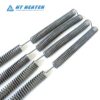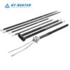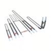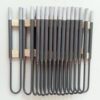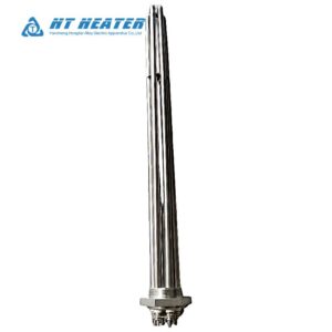
Sintered silicon carbide (SiC) delivers exceptional high-temperature radiant flux, but it remains a rigid, brittle ceramic with zero mechanical ductility. In industrial furnaces, premature rod fracture, terminal arcing, and localized wall melting are frequently traced back to improper SiC heating element installation—such as binding wall bores, misaligned support bridges, or taut terminal straps.
This engineering guide provides kiln designers and maintenance engineers with a step-by-step silicon carbide heating element installation protocol, covering pre-installation checks, SiC heater spacing, support clearances, and failure troubleshooting. If you are still finalizing element profiles and dimensions before installation, consult our foundational Silicon Carbide Heating Elements: Types, Shapes & Selection Guide.

1. Before Installing SiC Heating Elements: Pre-Installation Checklist
Before inserting any rod into the furnace chamber, complete these five verification steps to prevent mechanical binding or electrical imbalance:
Prepare Terminal Hardware: Verify that multi-layer aluminum braid straps and stainless steel spring clips (C-clamps or G-clamps) match the cold-end diameter and amperage rating.
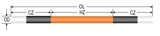
Verify Element Dimensions (HZ / CZ / OL): Confirm that the Hot Zone length (HZ) is shorter than or flush with the internal chamber span, and that Cold End lengths (CZ) match the refractory wall thickness plus external terminal clearance.
Inspect for Transit Damage: Check each rod, U-type crossbeam, and metallized aluminum terminal end for hairline cracks, chipped joints, or surface contamination.
Sort by Calibrated Hot Resistance: Check the factory calibrated resistance value (stamped in $\Omega$ on the cold end). Group elements with closely matched resistance values into the same series circuit.
Check Wall Bore Coaxial Alignment: Sight through opposite furnace wall feed-through holes (using a straight alignment rod if needed) to verify that opposing bores are coaxial and level.
2. SiC Heating Element Spacing and Furnace Clearances
Proper SiC heater spacing prevents mutual radiative shielding—where adjacent rods trap heat between one another—and ensures uniform chamber temperature distribution.
Note: In the table below, D denotes the outer diameter of the heating section (OD). Values represent common preliminary engineering references; final layout must account for chamber watt density and thermal uniformity targets.
| Spatial Clearance Dimension | Preliminary Design Reference | Engineering Purpose & Risk if Violated |
|---|---|---|
| Element Center-to-Center (S) | Minimum ≥ 2.0 × D; Recommended ≥ 2.5–3.0 × D | Prevents mutual radiative overheating between adjacent rods; wider spacing improves temperature uniformity at lower watt densities |
| Element to Wall / Roof / Hearth | ≥ 1.5–2.0 × D (typically ≥ 40–50 mm) | Allows free radiant dissipation; insufficient clearance overheats refractory bricks and creates hot spots on the rod backwall |
| Element to Workload / Charge | ≥ 1.5–2.5 × D | Prevents localized scorching of the product and reduces risk of mechanical impact during loading/unloading |
| Hot Zone (HZ) Wall Inset | Recessed 10–25 mm inside chamber wall | Critical Rule: The active Hot Zone must never enter the insulated wall bore, or trapped heat will melt the hot-to-cold weld joint |
3. How to Install SiC Heating Elements Step by Step
Follow this six-step sequence during new furnace assembly or SiC heating element replacement:
- Step 1 — Clean Openings & Insert Sleeves: Vacuum refractory debris from all wall feed-through bores and verify that ceramic wall sleeves sit flush and uncracked.
- Step 2 — Slide Elements Gently (Never Force): Insert the element horizontally or lower it vertically through the wall sleeve using two hands. Never force, hammer, or twist a rod through a misaligned hole.
- Step 3 — Center the Hot Zone (HZ): Position the element axially so that the central Hot Zone sits symmetrically inside the open chamber and both cold ends protrude equally outside the furnace shell.
- Step 4 — Verify Free Rotation & Axial Play: Gently rotate straight rods by hand ($360^\circ$) and slide them axially a few millimeters to confirm zero mechanical binding. Pack the annular gap between the cold end and sleeve loosely with soft ceramic fiber wool.
- Step 5 — Attach Braids & Spring Clamps: Slip the aluminum braid strap over the clean metallized terminal end and secure it with the spring clip. Ensure the braid hangs with a relaxed slack loop so it applies zero pulling or bending tension on the cold end.
- Step 6 — Perform Pre-Energizing Cold Checks: Verify series/parallel wiring against the schematic, confirm no aluminum braids touch grounded furnace steel, and reset the transformer tap to the appropriate starting voltage.
4. Supports, Wall Sleeves and Thermal Expansion
During heating and cooling cycles, refractory brickwork and ceramic elements expand at different rates. Accommodating SiC element thermal expansion without inducing shear or bending stress requires proper SiC heating element support geometry:
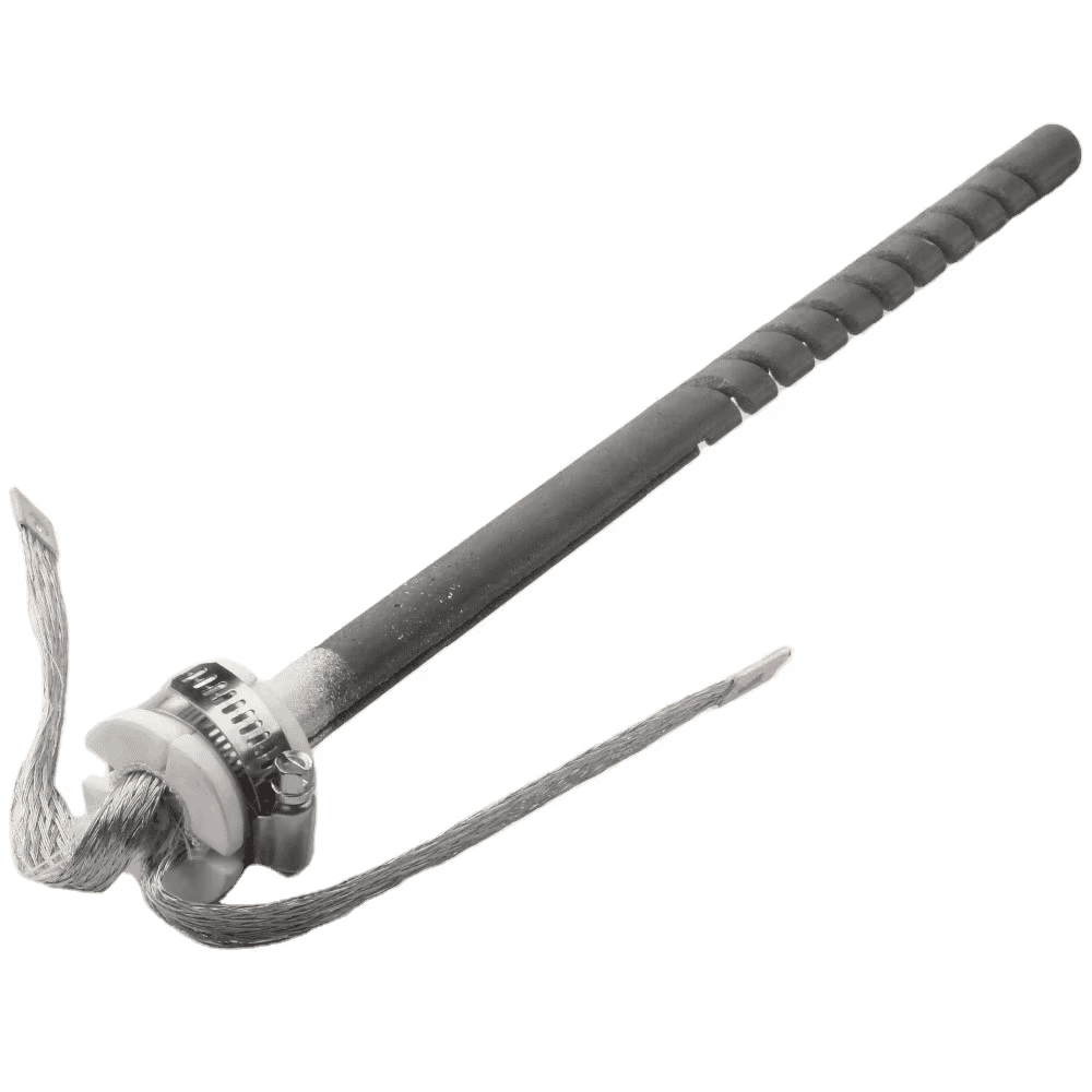
- Ceramic Wall Sleeves & Annular Clearance: Feed-through holes should be lined with high-alumina or mullite guide sleeves. As a general sizing guide, sleeve inner diameter (ID) is typically specified 3 mm to 6 mm larger than the cold-end outer diameter (for Dumbbell DB elements, size the bore to clear the enlarged cold end). Never cement or mortar a SiC rod into the furnace wall.
- Horizontal Multi-Leg (U / W Type) Support: When mounting long U-type or W-type elements horizontally, ensure both leg feed-through holes are level. In ultra-high-temperature chambers (>1400C) with wide spans, support the fused crossbeam end on a high-purity alumina refractory saddle or support brick to prevent high-temperature cantilever sag.
- Vertical Suspension & Axial Expansion Travel: Vertically hung elements support their weight via external insulating support collars resting on the furnace roof plate. Always leave unobstructed vertical clearance beneath the bottom tip (or below the U-bridge) to accommodate downward SiC element thermal expansion and refractory roof movement without bottoming out.
5. Terminal Connections and Electrical Safety
Reliable electrical contact at the cold ends prevents arcing and premature silicon carbide heater failure:
- Use Spring Clips Only (No Rigid Bolts): Fasten flexible aluminum braids using heat-resistant stainless steel spring clamps. Rigid bolted busbars or stiff copper cables transmit mechanical leverage that snaps brittle cold ends.
- Keep Metallized Ends Clean and Dry: Never apply conductive grease, anti-seize paste, or oil to the aluminum-sprayed terminal zone; organic compounds carbonize under heat and trigger severe arcing.
- Match Resistance & Verify Voltage Taps: Before energizing a newly installed bank, ensure elements in each series string are matched by stamped resistance and that SCR current limits and transformer taps are set correctly. For detailed calculations on series/parallel balancing and SCR tap adjustments, see SiC Heating Element Resistance: Aging, Power Control & Replacement.
6. Common SiC Heating Element Failures and Troubleshooting
When investigating a silicon carbide heater failure, inspect the fracture location and terminal condition to identify the underlying mechanical or thermal root cause:
| Observed Field Symptom | Potential Engineering Root Cause | Inspection & Corrective Action |
|---|---|---|
| Clean fracture near the inner wall face | Restricted thermal expansion, misaligned wall holes, or mortar binding the cold end | Check bore coaxial alignment with a straight rod; enlarge sleeve clearance and pack only with loose fiber blanket |
| Melting or burnout at the hot-to-cold joint | Hot Zone (HZ) shifted into the insulated wall bore, or ordered HZ exceeds chamber width | Re-center element axially; verify cold-end protrusion lengths and confirm HZ sits 100% inside the open chamber |
| Cracking at U-type or W-type bridge joints | Uneven leg hole alignment, twisted terminal clamps, or unsupported long horizontal span | Align dual wall bores; attach terminal clamps only after seating the element; add a ceramic support cradle if needed |
| Terminal arcing, blackening, or melted aluminum | Loose/annealed spring clamps, undersized braids, or surface contamination on metallized ends | Isolate power; replace fatigued spring clips and oxidized aluminum braids; clean terminal contact surfaces |
| Surface bubbling or rapid cracking after relining | High moisture/steam driven out of uncured refractory mortar during rapid initial heat-up | Follow a slow refractory dry-out ramp (100°C–600°C) with furnace vents open before running at full temperature |
7.SiC Furnace Maintenance Checklist
Consistent SiC furnace maintenance prevents unplanned kiln outages:
- Post-Installation Check (First 24 Hours): Verify uniform red/orange glow across all rods via sight ports and log initial zone voltage and amperage.
- Monthly Inspection: Check external spring clamps for tension loss, inspect loose fiber packing around cold ends to stop hot gas blow-by, and check aluminum braids for fraying.
- Pre-Replacement Logging: Record live branch resistance (R = V / I) monthly to plan scheduled SiC heating element replacement before the transformer reaches its maximum tap.
Partner with Hongtai for Engineered High-Temperature Furnace Heating Solutions
Minimizing premature rod breakage and maximizing kiln uptime requires precision-manufactured elements paired with proper mounting hardware.Hongtai Heater Factory manufactures custom industrial silicon carbide (SiC) heating elements—complete with matched refractory wall sleeves, multi-layer aluminum braids, and stainless steel spring clamps—engineered precisely to your chamber span and wall thickness specifications.
- Consult our Engineers: Send your wiring schematics to the Hongtai Heater Factory technical team for a free design review.
- Visit Us:: www.hongtai-heater.com