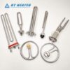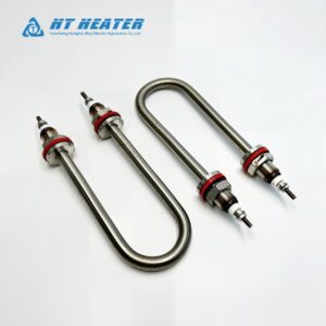
When sourcing custom OEM tubular heaters from a trusted tubular heater manufacturer, the accuracy of your engineering specification dictates both project velocity and production quality. Incomplete drawings or missing dimensional parameters inevitably lead to extended Design for Manufacturability (DFM) reviews, delayed sampling, and potential field failures.
A professional custom tubular heater drawing should define not only the final geometry but also the electrical, thermal, termination, material, mounting, and testing requirements. This guide walks B2B procurement managers and sourcing engineers through how to specify a tubular heating element and prepare a precise tubular heater RFQ specification to accelerate RFQ processing and ensure reliable mass production.
1.Geometric Dimensions: OD, Developed Length & Formed Shape
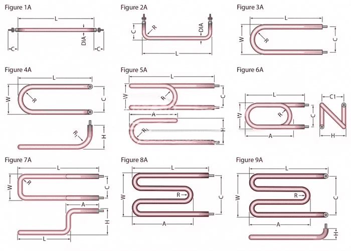
The physical geometry of a tubular heating element establishes its mechanical fit and total heat transfer area.
Outer Diameter (OD): Always specify the exact sheath diameter and required dimensional tolerance (typically +/- 0.05 mm to +/- 0.10 mm). Non-standard diameters require custom swaging dies, which can impact tooling lead times.
Developed Length (tubular heater developed length): Developed length (sometimes referred to as all-arm length or unformed length) is the linear tube length used for manufacturing and forming calculations. Because terminology varies by manufacturer, the drawing should explicitly define how the length is measured (e.g., measured along the tube centerline or neutral axis through the formed geometry). Providing the developed length ensures accurate material costing and resistance-wire calculation.
2.Heated Length, Cold Zones & Terminal Temperature
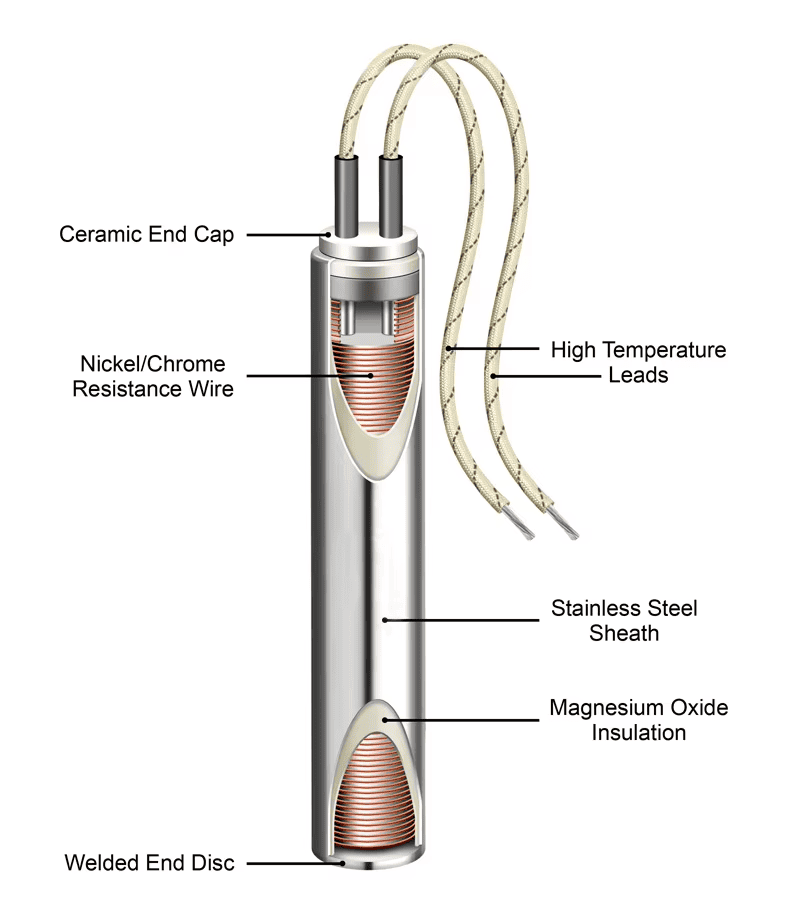
A tubular heater contains two functional zones: the active heated zone (where the internal resistance wire resides) and the inactive tubular heater cold zone (where solid steel terminal pins connect the wire to external circuits).
Why Cold Zone Specification is Critical:
The required cold length is determined not only by the terminal location but also by the allowable temperature of the seal, lead wire insulation, connector, and mounting hardware.
- Too Short: Conductive heat will migrate into the electrical terminals, degrading the seal and melting lead insulation.
- Too Long: For a fixed total power and sheath diameter, increasing the unheated length reduces the available heated surface area, which therefore increases the calculated tubular heater watt density and operating temperature of the active zone.
Engineering Best Practice: Where possible, position mounting bulkheads, bushings, and terminal seals within the designated unheated section so that these components remain well within their allowable temperature ranges.
3.Electrical Specifications: Voltage, Wattage, Current & Phase
Electrical parameters determine the internal wire gauge, coil pitch, and component sizing.
- Voltage (V) & Wattage (W): State the nominal operating voltage and total power output. Wattage tolerance is commonly specified as +5% / -10% for standard tubular elements, although tighter tolerances may be available by agreement. The applicable product standard and customer specification should be confirmed for each project.
- Current (I): Specify the operating current (I = P/V). This is crucial for properly sizing lead wires, terminal hardware, and control panel contactors.
4.Watt Density and Process Conditions
Watt density dictates the operating sheath temperature and must be carefully matched to the surrounding process medium to prevent fluid degradation or heater burnout.
Note: The following table provides illustrative watt density ranges. The final design requires a comprehensive application review considering fluid velocity, viscosity, outlet temperature, and scale potential.
| Process Application | Typical Design Reference | Common Sheath Material |
| Clean Water Heating | 6.0 – 10.0 W/cm² | SS 304 / SS 316L |
| Forced Air Heating | 3.0 – 5.0 W/cm² | SS 304 / Incoloy 840 |
| Light Oils / Hydraulics | 2.0 – 3.5 W/cm² | SS 304 / Steel |
| Refrigeration Defrost | 1.5 – 2.5 W/cm² | SS 304 (Vulcanized Seal) |
5.Terminal Types, Sealing & Mounting Hardware
The connection interface must be designed to withstand both mechanical stress and environmental exposure.
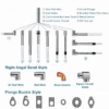
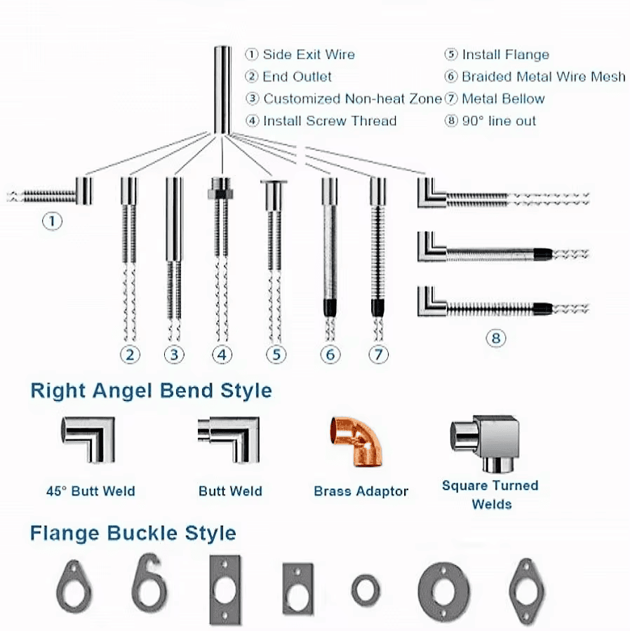
1.Terminal Types: Common options include threaded studs (M4/M5), quick-connect spades (6.3 mm), screw lugs, or high-temperature flexible lead wires crimped directly to the cold pin.
2.Terminal Seals: Always specify the required terminal temperature and environmental exposure rather than selecting a seal solely by material name.
- Epoxy / RTV Silicone: Flexible and suitable for many industrial applications; temperature limits depend heavily on formulation.
- High-Temperature Silicone: Used where higher terminal temperatures are expected.
- Ceramic / Hermetic: High-temperature ceramic or hermetic constructions can be used where conventional polymer seals are unsuitable (e.g., extreme heat or vacuum applications).
6.Tubular Heater Sheath Material Selection
Selecting the appropriate metal sheath prevents chemical corrosion and oxidation. Note: These are indicative high-temperature capabilities, not universal operating limits. Actual allowable temperature depends on the alloy, atmosphere, watt density, and construction.
- Stainless Steel 304: Up to ~650°C (General air/liquid heating).
- Stainless Steel 316L: Up to ~650°C (Corrosion-sensitive liquids).
- Incoloy 800: Up to ~870°C (High-temperature air and process heating).
- Incoloy 840: High-temperature air heating for ovens and appliances.
- Fluoropolymer Encapsulation (PTFE / PFA): Application-specific for highly aggressive chemical baths (operates at much lower temperatures than exposed metal sheaths).
7.Bend Radius and Forming Requirements
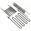
Setting the tubular heater minimum bend radius around 2x the sheath diameter (2x OD) is a useful preliminary design reference. However, the actual allowable radius depends on the sheath diameter, material, forming method, bend location, and whether the bend is factory-formed or field-formed. Always confirm the final radius capabilities with your tubular heating element manufacturer.
8.The Ultimate OEM RFQ Guide: Drawing & Testing Requirements
To transition swiftly from RFQ to production, ensure your engineering drawing explicitly details the following parameters and testing protocols.
What to Include on a Custom Tubular Heater Drawing:
- Outer Diameter (OD) and dimensional tolerances.
- Developed length (AAL) and final center-to-center dimensions.
- Heated length and tubular heater cold length (L1 / L2).
- Bend radii and formed geometry.
- Voltage, Wattage, and Phase.
- Sheath material and Seal type.
- Terminal type and precise location.
- Mounting fittings (e.g., flanges, threaded bushings).
Testing and Quality Requirements to Specify:
- Electrical: Resistance tolerance, insulation resistance (Meg-ohm), dielectric withstand (Hi-Pot), and leakage current.
- Dimensional: OD conformity, developed length, bend radius accuracy, and terminal retention strength.
- Application-Specific: Pressure testing for immersion heaters, moisture sealing tests for defrost heaters, or specific thermal cycling requirements.
Accelerate Your OEM Custom Heater Production
Clear engineering specifications eliminate prototyping delays and streamline volume manufacturing. Send your custom tubular heater drawing, CAD files, and testing specifications directly to the engineering team at Hongtai Heater Factory .artnering with a reliable tubular heating element OEM manufacturer ensures top-tier performance for your thermal systems.
- Consult our Engineers: Send your wiring schematics to the Hongtai Heater Factory technical team for a free design review.
- Visit Us:: www.hongtai-heater.com