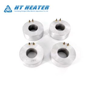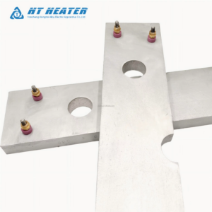
Designing Internal Tubular Element Cast-in Heaters requires strict engineering control to withstand high mechanical bending stresses, elevated foundry pouring temperatures, and intense hydraulic compression. In high-performance Internal Tubular Element Cast-in Heaters, embedded heating elements must maintain structural integrity without sheath cracking or dielectric breakdown. If the internal tubular element inside Internal Tubular Element Cast-in Heaters is bent improperly or insufficiently annealed prior to molten metal encapsulation, casting pressure can displace Nichrome resistance coils, fracture compacted Magnesium Oxide (MgO) insulation, or cause internal earth ground faults.
Mastering element forming standards, stress-relief annealing protocols, and foundry mold placement is essential to guaranteeing zero internal short circuits in Internal Tubular Element Cast-in Heaters.
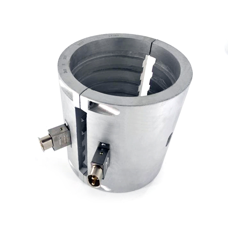
1. Bending Physics and Stretch Limits for Internal Tubular Element Cast-in Heaters
During element forming for Internal Tubular Element Cast-in Heaters, tube bending introduces severe tensile stress along the outer radius and compressive stress along the inner radius. When manufacturing Internal Tubular Element Cast-in Heaters, process engineers must calculate outer wall tensile strain (ε) to prevent work-hardening fractures:
Where:
- ε = Outer sheath wall tensile strain
- d = Outer diameter of the tubular element (mm)
- R = Centerline bend radius (mm)
In high-performance Internal Tubular Element Cast-in Heaters, if the centerline bend radius (R) drops below 2.5 to 3.0 times the element diameter (d), severe outer wall thinning occurs. Excessive strain compromises the internal MgO dielectric barrier, allowing the Nichrome resistance coil to drift toward the outer sheath wall—creating a catastrophic earth ground fault during high-pressure metal pouring.
2. High-Temperature Annealing Protocols for Internal Tubular Element Cast-in Heaters
Cold swaging and CNC tube bending induce work hardening, making stainless steel (SS304/SS316) and nickel-alloy (Incoloy 800/840) sheaths brittle. To restore grain structure ductility prior to foundry encapsulation, tubular elements used in Internal Tubular Element Cast-in Heaters must undergo full bright annealing:
When manufacturing Internal Tubular Element Cast-in Heaters, engineers enforce the following bright annealing requirements:
- Atmosphere-Controlled Furnacing: Elements are heated in an atmosphere-controlled furnace (cracked ammonia or dry hydrogen/nitrogen mix) to 1,020°C – 1,080°C for 10 to 15 minutes, followed by rapid quenching.
- Oxidation Elimination: Controlled atmospheres prevent surface oxidation and intergranular corrosion, ensuring a clean metallic surface for optimal thermal bonding with molten aluminum in Internal Tubular Element Cast-in Heaters.
- Ductility Restoration: Full annealing increases elongation capacity (>35%), allowing elements inside Internal Tubular Element Cast-in Heaters to flex slightly under molten metal impact without cracking.
Failure to eliminate internal casting voids around preformed elements can lead to thermal isolation barriers, as detailed in How Porosity Affects Heat Transfer in Cast-in Heating Elements.
3. Molten Metal Hydraulic Pressure Safeguards for Internal Tubular Element Cast-in Heaters
During permanent mold gravity or high-pressure die casting of Internal Tubular Element Cast-in Heaters, molten metal enters the mold cavity at temperatures exceeding 660°C (for aluminum) or 950°C (for bronze). High kinetic forces can displace unsupported heating elements.
To preserve sheath integrity in Internal Tubular Element Cast-in Heaters, technicians select sheath alloys based on thermal and yield strength parameters:
| Sheath Alloy Grade | Max Sheath Operating Temp | Annealing Temp Range | Post-Anneal Yield Strength | Primary Application in Cast-in Heaters |
| Stainless Steel 304 / 316 | 400°C – 500°C | 1,020°C – 1,050°C | Moderate (205 MPa) | Standard Internal Tubular Element Cast-in Heaters |
| Incoloy 800 / 840 | 650°C – 800°C | 1,050°C – 1,080°C | High (240 MPa) | High-Wattage Aluminum & Bronze Castings |
| Incoloy 825 / SS321 | 600°C – 750°C | 1,040°C – 1,070°C | High Corrosion Resistance | Finned Air & Liquid Cooled Castings |
For a broader evaluation of foundry alloys, compressive load limits, and thermal conductivity performance, consult our Cast-in Heater Material Selection Guide: Aluminum vs. Bronze vs. Iron.
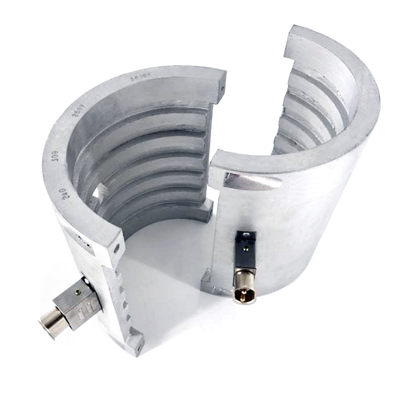
4. Quality Control Workflow for Internal Tubular Element Cast-in Heaters
Executing a rigorous quality control workflow ensures zero defect rates in Internal Tubular Element Cast-in Heaters before sending element preforms to the foundry floor:
- X-Ray Radiographic Inspection: Verify that internal Nichrome resistance coils inside Internal Tubular Element Cast-in Heaters remain centered within the MgO core along tight bend radii, maintaining dielectric clearance (≥ 1.0 mm).
- High-Voltage Dielectric Test (Hi-Pot): Apply 1,500V AC for 60 seconds between cold pins and the outer sheath to confirm zero insulation breakdown in Internal Tubular Element Cast-in Heaters.
- Cold Insulation Resistance Audit: Measure insulation resistance using a 1,000V DC megohmmeter to ensure dry readings exceed 500 MΩ.
Proper element positioning is equally critical when integrating forced air or water cooling tubes, as analyzed in Air Cooled Cast in Heater: Extruder Barrel Cooling Guide.. To specify precise tube dimensions, terminal studs, and voltage requirements during procurement of Internal Tubular Element Cast-in Heaters, review How to Specify Custom Cast-in Heaters for Industrial Machinery.
For heavy-duty processing equipment applications, see Extruder Barrel Cast in Heater: Blow Molding Thermal Guide. To review mounting procedures, check our Troubleshooting Cast-in Heater Failures: Internal Element Burnout and Warping or review standard band failure modes in Troubleshooting 101: 5 Common Causes of Band Heater Burn-Out. For liquid-tight die setups, see Brass Nozzle Heater: Eliminating Plastic Leakage Downtime.
For diagnostic protocols across Cast-in Band systems, consult How Porosity Affects Heat Transfer in Cast-in Heating Elements or explore our master engineering manual:Industrial Band Heaters: The Ultimate Engineering Guide to Selection, Efficiency & Troubleshooting (2026 Edition).