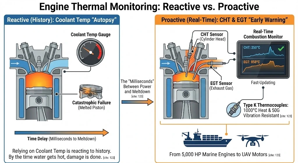
Introduction: The “Milliseconds” Between Power and Meltdown
The Hook: In a high-performance diesel generator or a racing engine, the difference between “Peak Efficiency” and “Catastrophic Failure” is often just a few seconds of thermal runaway.
If you are relying solely on your Coolant Temperature gauge, you are reacting to history. By the time the water gets hot, the piston may have already melted. Coolant temperature is an autopsy report; you need an early warning system.
The Solution: Only Cylinder Head Temperature (CHT) and Exhaust Gas Temperature (EGT) sensors provide real-time data on the combustion health inside the chamber.
Whether you are tuning a 5,000 HP marine propulsion engine or designing a UAV (drone) motor, the thermodynamic principles are identical.
The Promise: This guide moves beyond simple automotive hobbyist advice. We will explore the industrial engineering behind selecting Type K Thermocouples that can withstand 50G vibration and 1000°C heat without failing, ensuring your critical assets stay online.
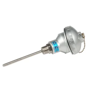
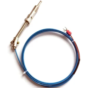
Mounting: A blind hole is drilled into the cylinder head casting. An adapter is screwed in, and the spring-loaded probe is locked in place.
Advantage: The spring ensures positive contact with the bottom of the hole, eliminating air gaps and vibration noise.
Cylinder head temperature vs exhaust gas temperature sensor placement diagram.
The EGT Sensor: Surviving the “Fire Stream”
Measuring gas at 800°C+ while vibrating at 10,000 RPM is the ultimate torture test for a sensor.
Why Type K is King
For EGT, you have one choice: Type K (Chromel-Alumel).
Why not Type J? Type J (Iron) oxidizes rapidly above 760°C. Since diesel exhaust often hits 850°C and gasoline exhaust hits 950°C, Type J will rust and fail within hours.
Why not Platinum RTD? RTDs are too fragile for the vibration and too slow to catch the rapid spikes of EGT.
Probe Placement Strategy
Distance: The “Goldilocks Zone” is 100mm (4 inches) from the cylinder head exhaust port.
Too Close: The flame front might still be burning, giving erratic readings.
Too Far: The gas cools down, masking a “Lean” condition.
Depth: The probe tip must be in the Center of Gas Flow. If it touches the pipe wall, it will read low (heatsink effect).
Response Time Dilemma
Exposed Tip: The junction is bare.
Pros: Instant response (0.1s). Great for tuning racing engines.
Cons: Weak. Carbon fouling can bridge the wires.
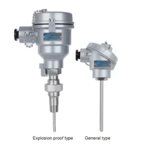
Grounded Sheath: The junction is welded to the sheath tip.
Pros:Indestructible. The standard for Industrial Generators.
Cons: Slower (0.5s), but fast enough for monitoring.
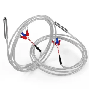
The Pain: On a massive marine diesel engine, the vibration is powerful enough to shatter teeth. Standard “Tube-and-Wire” sensors (with ceramic beads) will disintegrate internally. The beads turn to dust, and the wires short out.
The Solution: You must use Mineral Insulated (MI) Cable.
Construction: The wires are encased in highly compressed Magnesium Oxide (MgO) powder inside an Inconel 600 sheath.
The Result: The sensor is solid as a rock but flexible as a wire. It absorbs vibration without internal movement.
Don’t let a bad install ruin a good sensor. Follow these 3 rules.
1. Strain Relief (The Service Loop)
Never run the wire tight from the probe. Vibration will snap the wire right at the transition pot.
Action: Leave a 10cm (4 inch) loop of wire (a “Service Loop”) and zip-tie it to a nearby bracket. This loop acts as a shock absorber.
2. Shielding (The Noise Killer)
High-voltage ignition coils and injectors create massive EMI (Electromagnetic Interference).
Action: Specify EGT sensors with Stainless Steel Overbraid (SSB). Ground the shield at the ECU end only.
3. Fitting Selection
Avoid fixed-welded threads if possible.
Action: Use a Compression Fitting. This allows you to slide the probe in and out to center the tip perfectly in the exhaust stream before tightening.
Air fuel ratio vs exhaust gas temperature relationship chart.
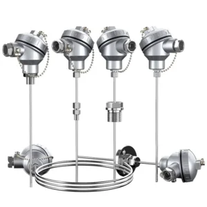
CHT/EGT Product Selection Matrix
Use this table to pick the right sensor for your machine.
Application
Recommended Sensor
Probe Type
Max Temp
Key Feature
Diesel Genset (Backup)
EGT Probe
6mm Grounded MI (Inconel)
900°C
Vibration Proof, Long Life
UAV / Drone Engine
CHT Ring
10mm / 12mm / 14mm Ring
300°C
Lightweight, fits under spark plug
Racing Car / Tuning
Fast EGT
3mm Exposed Tip
1100°C
<0.1s Response Time
Marine Propulsion
Heavy Duty EGT
8mm Inconel Sheath
850°C
Salt/Corrosion Resistant
Air-Cooled Porsche/VW
CHT Ring
Ring Terminal
250°C
Monitor head cooling
Frequently Asked Questions (FAQ)
What is a normal Cylinder Head Temperature (CHT)?
For air-cooled engines, normal CHT is typically between 150°C and 200°C (300°F – 400°F). Temperatures climbing above 230°C (450°F) are in the “Red Zone,” where aluminum alloys lose structural strength and can warp, leading to dropped valve seats. Water-cooled engines run much cooler, typically mirroring the coolant temperature (90°C – 110°C).
Where should I install my EGT probe?
Ideally, install the probe on the exhaust manifold runner, about 50mm to 100mm (2-4 inches) from the cylinder head exhaust port. This ensures you measure the hottest gas before it cools down in the pipes or turbocharger. For turbo engines, always measure Pre-Turbo for safety tuning.
Why do EGT sensors fail?
The #1 cause is vibration fatigue, followed by carbon buildup and thermal shock. Using a cheap “tube and bead” sensor on an engine is a recipe for failure. Upgrading to a high-quality Mineral Insulated (MI) probe with proper strain relief loops can extend sensor life by 5x.
Can I use a Type J thermocouple for EGT?
No. Type J (Iron-Constantan) oxidizes rapidly and scales (rusts) above 760°C. Since gasoline and high-performance diesel exhaust gases often exceed 800°C-900°C, the iron wire will fail quickly. Type K (NiCr-NiAl) or Type N is required for longevity in exhaust streams.