When an industrial electric furnace suffers from sluggish ramp rates, zones failing to reach setpoint, or nuisance breaker trips, blindly replacing an entire bank of heating elements rarely cures the underlying issue. Most industrial furnace heating element troubleshooting incidents are not random manufacturing defects—they are the cumulative result of progressive resistance drift, degraded terminal clamping, furnace atmosphere contamination, or localized radiative heat traps.
Effective industrial heater troubleshooting connects field instrument measurements (isolated resistance, megohm insulation checks, and live operating V/I ratios) directly to physical fracture signatures. This guide provides maintenance supervisors and field service engineers with an actionable diagnostic sequence from electrical isolation to root-cause corrective action. (To optimize chamber spacing and eliminate hot spots in new or retrofitted layouts first, consult furnace heating element layout).
1. Safety Isolation & Four-Step Field Diagnostic Workflow
Before opening a furnace door or dismantling terminal busbars, electrically isolate the faulted branch. Never apply a high-voltage insulation tester (Megger) while SCR power controllers, transformers, or temperature sensors remain wired to the heater circuit—doing so can permanently destroy semiconductor gates and control inputs.
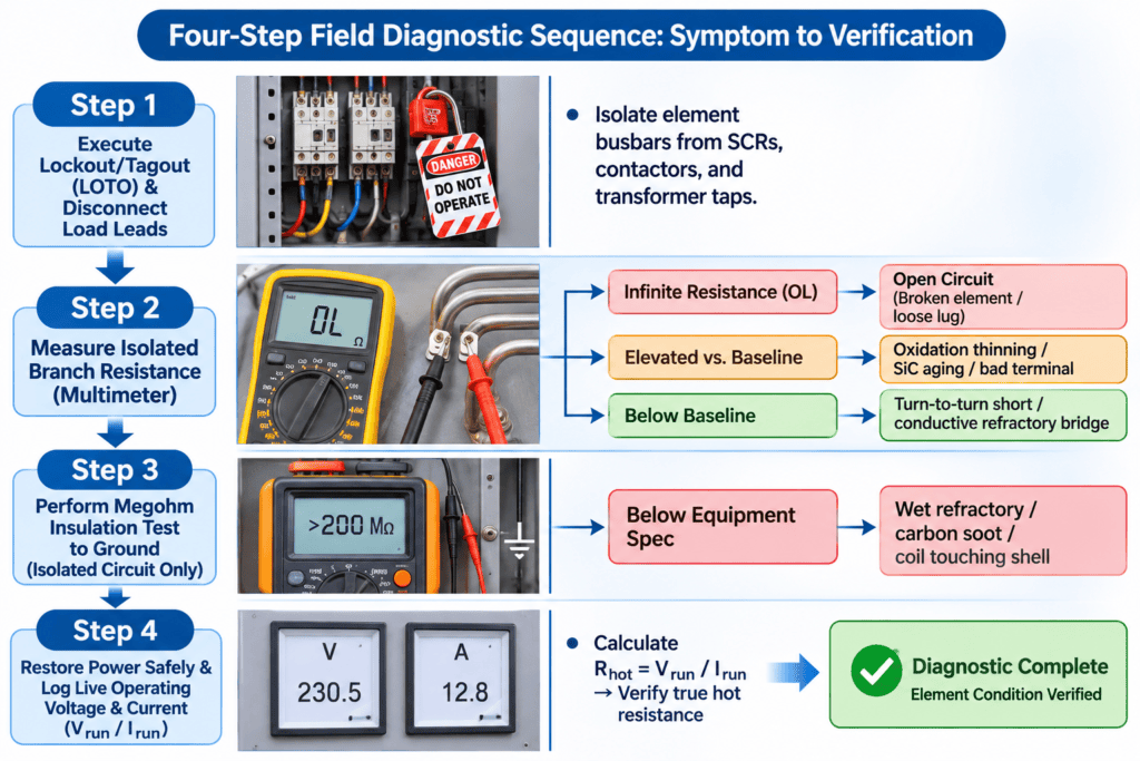
Interpreting Field Measurements Accurately
- Always Compare Against Commissioning Baselines: A single resistance reading means little without context. Compare measured values against your furnace’s commissioning log and the element manufacturer’s datasheet for the exact alloy grade and measurement temperature.
- Cold Tightness Does Not Guarantee Hot Continuity: Terminal bolts that feel secure at room temperature can loosen and oxidize as busbars expand at operating temperature. When cold resistance reads normal but a zone loses kW during heat-up, measure live branch amperage with a clamp meter and scan external terminal straps with an infrared camera.
- Distinguish Normal Thermal Curves from Faults: Metallic alloys (NiCr/FeCrAl) show a modest resistance rise from room temperature to operating heat, whereas MoSi2 elements exhibit a steep Positive Temperature Coefficient (PTC) where hot operating resistance climbs roughly 8× to 14× above its 20°C value. Always verify your readings against the specific alloy’s resistance-temperature curve rather than assuming a dead short.
2. Material-Specific Resistance Drift & Replacement Rules
Furnace heater power loss is most commonly caused by rising circuit resistance. Per Joule’s Law (P = V^2 / R), at a fixed supply voltage, any upward drift in circuit resistance directly reduces thermal wattage output. However, diagnostic criteria and replacement rules differ sharply across element chemistries (see industrial furnace heating element materials):
| Element Material | Normal Resistance Behavior Over Time | Primary Causes of Abnormal Electrical Readings | Maintenance & Replacement Matching Rule |
| Metallic Alloys (NiCr / FeCrAl) | Relatively stable across service life; drifts upward gradually as surface oxidation thins the wire cross-section | Severe local necking at hot spots; oxidized cold-pin welds; loose external terminal clamping | Compare individual coils at room temperature against initial baseline records; inspect and re-torque terminal lugs before condemning coils |
| Silicon Carbide (SiC) | Rises continuously with operating hours as internal and surface SiO2 oxidation narrows the conductive core | End-of-life resistance escalation; accelerated oxidation in wet or reducing atmospheres; degraded aluminum end-spray | Do not rely solely on cold resistance—calculate true operating resistance (R_hot = V_run / I_run) at stable high temperatures (>1000°C). Match resistance values per supplier grouping rules for both series and parallel circuits |
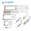
| Molybdenum Disilicide (MoSi2) | Stable hot operating resistance; no gradual aging resistance drift under normal conditions | Low-temperature intergranular oxidation (“pesting” around 400°C–600°C); loose or arced aluminum terminal braids | Individual failed elements can typically be replaced singly without replacing the entire bank, provided the spare matches exact grade, geometry, and cold/hot resistance tolerances |
Why SiC Resistance Matching Matters in Both Series and Parallel Circuits
- In Parallel Circuits: Wiring a brand-new, low-resistance SiC rod in parallel with aged, high-resistance rods forces the new element to draw disproportionately high current (I = V / R), overloading its surface watt density and causing premature burnout.
- In Series Circuits: Mixing high-resistance aged elements with low-resistance new elements skews voltage division (V = I × R), forcing the highest-resistance rod in the string to dissipate excessive wattage and fail early. Always match replacement SiC elements within the manufacturer’s specified resistance tolerance band.
3. Physical Root Causes of Element Burnout & Open Circuits
Inspecting the fracture surface of an open circuit heating element and surrounding refractory brick provides unmistakable forensic clues:
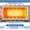
3.1. Mutual Radiation Traps & Localized Overheating
- Fracture Signature: Several adjacent turns of a helical coil melt and fuse together into a solid metallic bead, while the rest of the coil appears healthy.
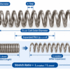
- Root Cause: Uneven coil stretching during installation, localized sag from inadequate ceramic support spans, or accumulated conductive debris (oxide scale, fallen workpieces) in hearth grooves trapped radiant heat between adjacent turns, pushing local metal temperature past its melting threshold. (For proper spacing and support intervals, consult heating element coil pitch and spacing).
3.2. Furnace Atmosphere & Chemical Contamination
- Signature A (Dull Green, Crumbly Powder Surface — “Green Rot”): Occurs when NiCr alloys operate roughly between 800°C and 1050°C in weakly oxidizing or oxygen-depleted atmospheres (such as cracked ammonia or poorly dried endothermic gas). Chromium oxidizes internally along grain boundaries rather than forming a continuous protective surface film. (See NiCr heating wire alloy properties).
- Signature B (Brittle, Granular Fracture with Melted Craters): Points to sulfur contamination from uncleaned cutting oils, drawing lubricants, or sulfur-bearing refractories. Above ~645°C, sulfur reacts with nickel to form low-melting nickel-sulfide eutectics that eat rapidly through the wire.
- Signature C (Glassy Slag & Pitting at Refractory Contact Points): Free silica (SiO2), iron oxide (Fe2O3), or alkali fluxes in low-grade ceramic supports react with the element’s protective oxide scale at elevated temperatures, fluxing away the passivating glaze.
3.3. Mechanical Stress, Creep & Cold Brittleness
- Signature: Clean, flat brittle snap with minimal cross-sectional thinning.
- Root Cause: Ferritic FeCrAl alloys undergo irreversible grain growth during prolonged high-temperature service, leaving coils very brittle once cooled to room temperature—avoid bending, hammering, or re-stretching aged FeCrAl coils during cold maintenance. In MoSi2 installations, rigid terminal clamps that block thermal expansion or excessive startup current generating Lorentz-force repulsion will snap the brittle cold shanks (see MoSi₂ heating element failure).
4. Terminal, Transformer & SCR Power Control Faults
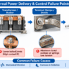
In many service calls, the heating elements inside the chamber are undamaged, and furnace heater power loss originates in the external power delivery system:
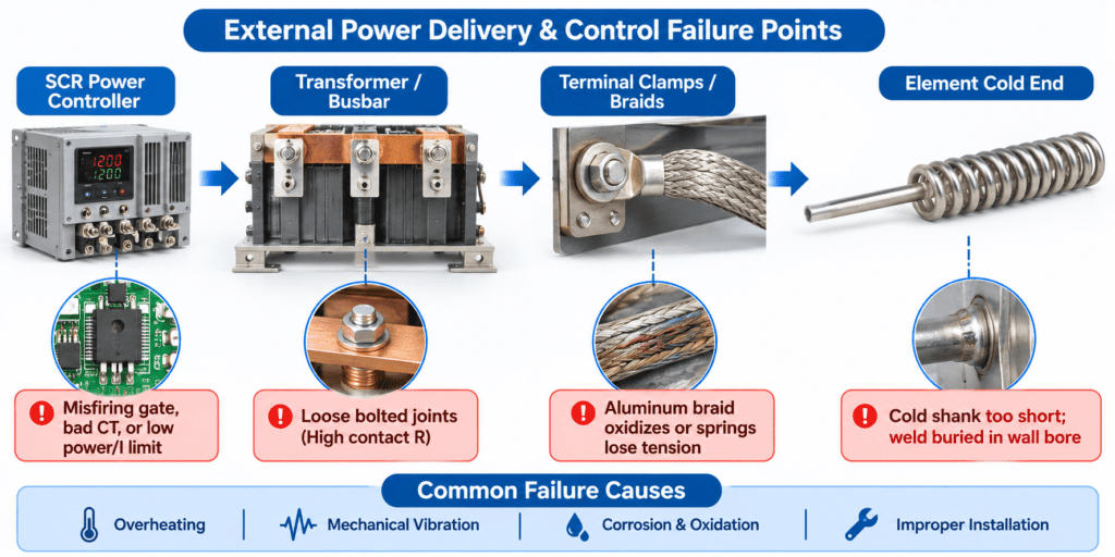
- Layered SCR Controller Diagnostics: When an SCR-controlled zone underperforms, do not assume the current-limit setting is the sole culprit. Check in sequence: (1) incoming supply phases and ultra-rapid semiconductor fuses, (2) 4–20 mA / 0–10 V control command signal from the temperature controller, (3) feedback current transformer (CT) wiring and ratio settings, and (4) firing-angle output across each SCR phase leg.
- Three-Phase Imbalance & Open Branches: Depending on whether your furnace is wired in Wye (star), closed Delta, or open Delta—and how many parallel strings exist per phase—an open branch or blown phase fuse alters total zone kW non-linearly. Always reference the furnace’s specific electrical schematic when interpreting phase current drops.
- Degraded External Clamping: Thermal cycling loosens standard flat nuts over time, spiking contact resistance and burning off terminal studs. Clean oxidized contact surfaces and install high-temperature stainless steel Belleville spring washers to preserve constant clamping force.
5. Comprehensive Furnace Heating Element Troubleshooting Matrix
| Observed Field Symptom | Diagnostic Measurement Findings | Probable Physical / Electrical Root Cause | Corrective & Preventive Action |
| Furnace ramps slowly and fails to reach maximum temperature | Incoming line voltage normal, but live clamp amperage is below rating; isolated resistance reads high | 1. SiC elements aged and increased in operating resistance 2. One or more parallel branches are open-circuited 3. SCR firing angle limited by fault, bad CT, or low power cap | 1. Isolate branches and calculate hot V/I resistance 2. Step up transformer tap or install resistance-matched replacements 3. Verify SCR command signal, CT feedback, and fuses |
| Single zone repeatedly burns out elements in the exact same location | Localized fused coil turns or severe wire necking; adjacent zones perform normally | 1. Localized tight coil pitch or debris causing a radiation trap 2. Damaged or mispositioned control TC causing local over-firing 3. Leaking door gasket forcing continuous 100% duty cycle | 1. Install uniformly stretched coils with proper support spacing 2. Calibrate control TC and verify insertion depth 3. Replace worn high-temperature door seals |
| Ultra-rapid fuses or main breaker trip immediately upon startup | Isolated Megger reading falls below equipment spec; or cold phase resistance reads abnormally low | 1. Sagged coil touching metallic shell or conductive brick 2. Moisture or carbon soot bridging refractory insulation 3. MoSi2 cold-started without phase-angle current limiting | 1. Vacuum carbon soot/scale and dry out furnace lining 2. Re-seat sagged coils and add ceramic support pins 3. Configure SCR cold-start current limit (see MoSi₂ startup current and SCR control) |
| Element snaps cleanly inside the refractory wall penetration bore | Chamber coil looks intact; open circuit is hidden inside the wall sleeve | 1. Thin active wire run through wall without a heavy cold pin 2. Cold-pin weld joint buried inside insulation instead of protruding into chamber | 1. Specify elements with welded heavy-gauge solid cold pins 2. Ensure weld joint clears hot wall face; pack sleeve loosely with ceramic fiber |
| External terminal lugs or aluminum braids overheat and discolor | Internal element resistance reads normal; IR camera detects hot external terminal connections | 1. Clamping bolts loosened without Belleville spring washers 2. Unsealed wall penetration leaking hot furnace gas onto lugs | 1. Buff oxidized contact faces and install stainless Belleville spring washers 2. Seal annular wall tube gaps with high-temp ceramic fiber |
6. Maintenance Records, PM Checklist & FAQs
Keeping Actionable Failure & Resistance Logs
Maintaining a simple zone-by-zone baseline log dramatically cuts troubleshooting downtime. Record commissioning cold resistance, steady-state hot voltage/amperage at a fixed reference temperature, and isolated insulation resistance after every major rebuild or element change.
Preventive Maintenance Checklist
- Every Scheduled Outage / Cleanout: Vacuum metallic oxide scale, dropped hardware, and carbon dust out of hearth grooves and refractory joints; visually inspect coils for sagging, bunched turns, or surface blistering.
- Quarterly Live Load Audit: Record steady-state clamp amperage across every phase and branch against commissioning baselines; scan external busbars, braids, and terminal lugs with an infrared camera.
- Semi-Annual Torque & Megger Inspection: With power locked out and load leads isolated from sensitive electronics, re-torque external spring-loaded terminal fasteners and record insulation resistance per equipment manufacturer guidelines.
Partner with Hongtai for Fast Replacement Elements & Root-Cause Support
Restoring production after an unexpected furnace shutdown requires both accurate root-cause diagnosis and replacement elements built to exact dimensional and electrical tolerances.Hongtai Heater Factory supplies industrial furnace operators and maintenance teams worldwide with precision replacement elements—including variable-pitch NiCr and FeCrAl helical coils, resistance-matched silicon carbide heating elements,high-purity MoSi₂ heating elements, and complete terminal clamping hardware.
- Consult our Engineers: Send your wiring schematics to the Hongtai Heater Factory technical team for a free design review.
- Visit Us:: www.hongtai-heater.com