In aerospace heat treatment, automotive carburizing, and technical ceramic sintering, an industrial furnace is only as reliable as its effective work zone during a Temperature Uniformity Survey (TUS) under standards such as AMS 2750 or CQI-9. Yet, even furnaces equipped with high-precision PID controllers and premium alloys frequently fail uniformity audits due to cold pockets, door-zone heat sinks, or localized radiant hot spots.
Achieving tight furnace temperature uniformity requires aligning spatial power delivery with the chamber’s actual heat-loss profile—and verifying that layout under real workload conditions. This guide breaks down the engineering logic behind industrial furnace heating element layout, covering zone power allocation, element spacing, furnace-type constraints, multi-zone control, and TUS validation. (To match element materials to your operating temperature and atmosphere first, consult industrial furnace heating elements).
1. Chamber Heat-Loss Balance & Zone Power Allocation
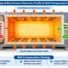
No furnace enclosure loses heat uniformly. During both ramp-up and steady-state soaking, thermal energy escapes fastest through structural discontinuities—door gaskets, hearth piers, cooling jackets, and refractory penetrations. Distributing kW equally across all interior surfaces guarantees cold zones wherever heat losses peak.
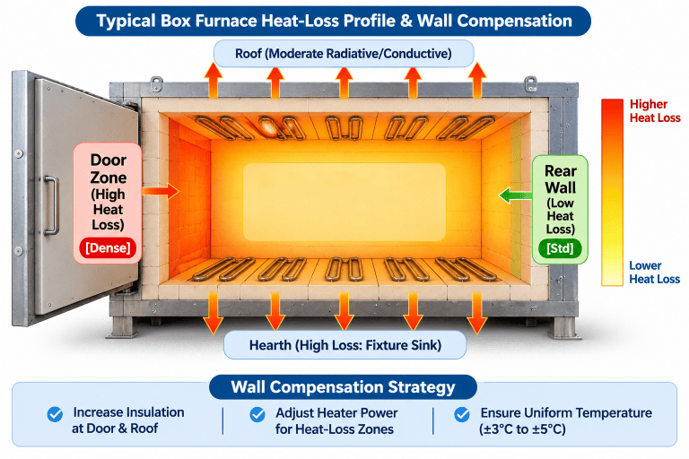
How Engineers Allocate Power Across Furnace Surfaces
Rather than guessing wall wattages, power allocation starts by summing three thermal loads per zone: steady-state wall/door conduction losses, atmosphere/seal infiltration losses, and transient workload/fixture thermal mass.
- Two-Side Heating (Left and Right Walls Only): Economical and mechanically simple. Best suited for narrow chambers or processes with wider temperature tolerances. In wide chambers, two-side layouts leave a cooler thermal valley down the center of the load.
- Three-Side Heating (Sidewalls + Under-Hearth): The standard baseline for industrial box heat-treating furnaces. Under-hearth elements—typically shielded beneath high-conductivity silicon carbide (SiC) hearth plates—offset conductive floor losses and heat heavy alloy trays from below, eliminating vertical top-to-bottom stratification.
- Four- to Five-Side Heating (Walls, Hearth, Roof, and Door): Essential for tight-tolerance furnaces (±3°C to ±5°C) and large car-bottom kilns. Adding roof elements and door-mounted heating panels neutralizes cold-door heat sinks and eliminates upper radiative blind spots.
2. Element Spacing, Edge Compensation & Radiative View Factors
Heating element spacing governs both individual element surface loading and the uniformity of radiant heat flux reaching the workload surface.
2.1 Edge & Door-Zone Compensation
Heat leakage around door seals, unheated vestibules, and axial conduction losses at the ends of tube furnaces depress end-zone temperatures relative to the chamber interior.
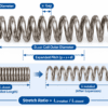
- Engineering Approach: Calculate the localized heat loss at the door or tube ends and increase installed power density across the outer 15% to 25% of the chamber length accordingly. Depending on door insulation thickness and cycling frequency, engineers commonly start with 15% to 30% higher power density in edge zones—achieved by tightening center-to-center rod spacing or using variable-pitch helical coils—and fine-tune output via independent zone trim.
- Thermal Safety Check: Whenever elements are spaced closer together, verify mutual radiation view factors so adjacent elements do not overheat one another (see coil spacing guidelines in heating element coil pitch and spacing).
2.2 Element Spacing (S) vs. Workload Clearance (H)
Discrete rod elements (such as silicon carbide heating elements) and wall-mounted coils emit thermal energy in overlapping conical patterns.
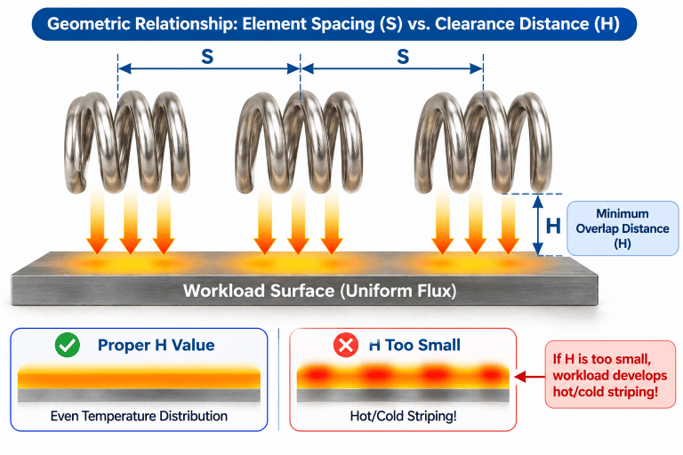
- View-Factor Principle: The distance (H) between the heating element plane and the effective work-zone boundary must be sufficient for adjacent radiation cones to merge into a uniform thermal plane. As a general layout starting point, engineers often keep clearance H roughly comparable to center-to-center element spacing S (typically around 0.8S to 1.2S for open rod arrays), adjusting based on whether diffuser plates, muffles, or recirculating fans are present. Placing parts too close to bare elements creates alternating hot stripes directly opposite each element and cooler shadow bands between them.
3. Furnace Architecture & Heat Transfer Regimes
Industrial furnace temperature distribution depends heavily on the dominant heat transfer mechanism at your operating temperature and the physical geometry of the furnace.
3.1 Temperature Regimes: Convection vs. Radiation
- Lower-Temperature Processing (< 650°C): Radiant heat transfer (which scales with absolute temperature to the fourth power, T^4) is relatively weak. Forced convection dominates. Without high-temperature recirculation fans and engineered airflow baffles, stagnant corners lag behind during ramp-up while parts facing bare elements overheat via direct radiation.
- High-Temperature Processing (> 800°C): Thermal radiation becomes the primary heat-transfer mechanism (though forced atmosphere circulation still aids uniformity in carburizing and tempering furnaces). Line-of-sight geometry, wall emissivity, and fixture openness dictate temperature spread.
3.2 Layout Constraints Across Furnace Types
| Furnace Type | Primary Heat Transfer & Uniformity Challenge | Key Element Layout Strategy |
| Batch Box Furnace | Severe heat loss at the front door and conductive sink through the hearth | Combine 3- to 5-side heating with dense door-zone compensation and SiC-covered hearth elements |
| Pit & Car-Bottom Furnace | Vertical thermal stratification (“chimney effect”) and massive car/hearth thermal mass | Split elements into independent upper and lower vertical zones; integrate hearth heating in the car |
| Continuous Belt / Pusher Furnace | Open entry/exit vestibules and continuous cold workload thermal drag | Concentrate higher kW capacity in entry preheat zones; divide length into sequential soak zones |
| Vacuum Furnace | Zero convective heat transfer—heat moves exclusively by line-of-sight radiation | Arrange elements in full 360° cylindrical or multi-sided arrays around the hot zone with multi-layer radiation shields |
4. Multi-Zone Control & Thermocouple Placement
When chamber aspect ratios become elongated, thermal losses vary significantly across walls, or workload density shifts between batches, a single control loop cannot hold tight uniformity across the entire chamber.
4.1 Logical Zone Partitioning
Rather than relying on an arbitrary chamber length cutoff, divide a furnace into independent control zones whenever local heat losses, convective patterns, or workload thermal loads differ across the chamber:
- Longitudinal Zoning (Front / Center / Rear): Allows high-loss door and rear-wall zones to modulate power independently from the insulated center soak zone.
- Vertical Zoning (Top / Bottom): Essential in deep pit or tall box furnaces to prevent natural buoyancy from overheating upper work layers.
4.2 Control Thermocouple (TC) vs. Survey Thermocouple Placement
Incorrect sensor placement frequently causes a furnace to read perfectly on the main controller while failing an independent TUS survey:
- Avoid Direct Element Line-of-Sight: Mounting a control thermocouple too close to an exposed heating element causes direct radiative heating of the sheath. The controller throttles power prematurely while the workload core remains under-heated.
- Avoid Recessed Refractory Bores: Burying a thermocouple tip inside a thick brick hole introduces severe thermal lag, triggering wide temperature overshoot during ramp cycles.
- Best-Practice Mounting: Position the control thermocouple tip in a representative thermal stream between the heating elements and the work-zone boundary—protruding clear of the refractory wall boundary layer without sitting directly in front of a bare element.
5. Empty vs. Loaded Conditions & TUS Validation
Optimizing furnace heating element layout improves thermal symmetry, but compliance with AMS 2750, CQI-9, or customer specifications is proven only through a calibrated Temperature Uniformity Survey (TUS).
- Define the Effective Work Zone: TUS sensors are placed at the extreme corners and center of the defined work zone—not against the furnace walls. If a furnace struggles to meet ±5°C at the outer edges, shrinking the certified work-zone envelope slightly away from door and wall gradients is often the most practical engineering adjustment.
- Empty vs. Loaded Performance: Passing an empty-chamber TUS does not guarantee loaded uniformity. Dense part loads and heavy fixtures block line-of-sight radiation (shadowing effect) and absorb large amounts of heat during ramp-up. Loaded TUS validation often requires open-grid fixtures, controlled part spacing, and longer thermal soak times so heat conducts evenly into the workload core.
6. Temperature Uniformity Troubleshooting Matrix
| Observed Uniformity Anomaly | Probable Layout, Control, or Aging Root Cause | Field Verification & Corrective Action |
| Door zone consistently runs colder than chamber center | Worn door seals; insufficient edge element power density; missing independent door zone | Replace door fiber seals; increase edge element density or bias door-zone SCR power upward |
| Tight soak uniformity, but wide spread during rapid ramp | Zone kW ratings mismatched to local thermal mass; low-loss center zone reaches setpoint early | Cap maximum output percentage on low-loss zones so all zones climb at an identical ramp rate |
| Upper work zone runs hotter than bottom hearth layer | Missing under-hearth elements; natural thermal stratification in tall chambers | Add SiC-covered hearth elements; split vertical wall elements into upper/lower control zones |
| Localized scorching on parts facing bare elements | Element spacing (S) too wide relative to clearance (H), or workload stacked outside certified work zone | Increase clearance H; tighten element spacing S; add refractory diffuser plates or baffles |
| Uniformity drifts after months of high-temp service | Resistance aging in SiC branches, oxidized terminal joints, or localized element thinning | Measure branch amperage with a clamp meter; re-match aged SiC groups |
Partner with Hongtai for Precision-Engineered Furnace Heating Layouts
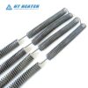
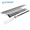
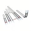
Achieving strict ±3°C to ±5°C temperature uniformity requires coordinating element spacing, edge-loss compensation, and balanced multi-zone electrical circuits.Hongtai Heater Factory manufactures custom industrial heating assemblies tailored to your exact chamber geometry—including variable-pitch NiCr and FeCrAl helical coils, resistance-matched silicon carbide heating elements,high-purity MoSi₂ heating elements, and multi-zone tubular heater banks.
- Consult our Engineers: Send your wiring schematics to the Hongtai Heater Factory technical team for a free design review.
- Visit Us:: www.hongtai-heater.com