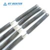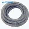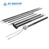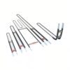
Sizing electric resistance elements for industrial ovens, duct banks, or tubular heaters requires more than applying Ohm’s Law to room-temperature resistance. Two common engineering miscalculations frequently cause field issues: designing strictly from cold multimeter readings (which causes delivered hot power to drop below setpoint), and calculating wattage without verifying the actual heating wire surface temperature and convective heat transfer limits.
An accurate nichrome heating wire calculation connects electrical ratings, cross-sectional geometry, alloy temperature correction factors (Ct), cold-start inrush margins, and surface watt density into a closed engineering design loop. This guide provides the step-by-step mathematical framework and a fully verified design example. To evaluate raw alloy chemistry and continuous temperature limits first, consult our alloy selection guide: Nichrome Heating Wire: Alloy Grades, Resistance & Temperature Selection.

1. Governing Formulas & Design Progression
Heating coil engineering follows a systematic sequence: Target Power & Voltage -> Operating Hot Resistance -> 20°C Baseline Cold Resistance -> Wire Diameter -> Extended Length -> Surface Watt Loading & Inrush Verification.
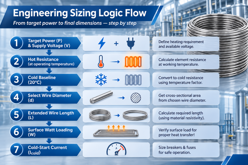
Core Mathematical Equations
- Operating Hot Resistance (Rhot): Rhot = V2 / P
- Cold Baseline Resistance at 20°C (R20): R20 = Rhot / Ct (Important Boundary Condition: Ct is the resistance-temperature factor of the specific alloy grade at the wire’s actual operating surface temperature, not the air or process chamber setpoint).
- Cross-Sectional Area (A): A = (π × d2) / 4
- Extended Wire Length (L): L = (R20 × A) / ρ (Where ρ is the electrical resistivity at 20°C in μΩ·m or Ω·mm²/m.
- Surface Watt Density (W): W = P / (π × d × L) (W/cm2)
- Cold-Start Current (Icold): Icold = V / R20
2. Common Nichrome Engineering Constants
Material constants vary slightly depending on alloy purity, melt chemistry, and cold-reduction schedules. The baseline values below represent typical commercial data for standard Ni-Cr formulations (such as Nikrothal / Cr20Ni80):
| Alloy Grade | 20°C Resistivity ρ (μΩ) | Max Continuous Element Temp | Ct Factor at 800°C | Ct Factor at 1000°C | Density (g/cm3) |
| NiCr 80/20 | 1.09 ± 0.03 | 1200°C | 1.04 | 1.05 | 8.40 |
| NiCr 70/30 | 1.18 ± 0.04 | 1250°C | 1.03 | 1.04 | 8.10 |
| NiCr 60/15 | 1.12 ± 0.03 | 1150°C | 1.08 | 1.10 | 8.20 |
Data Note: Verify exact Ct and resistivity tolerances against your material test report (MTR) or supplier datasheet prior to final production tooling.
3. Step-by-Step Worked Example: 220V / 2000W Forced-Air Coil
Design Objective: Size an open-coil helical heating element for a forced-convection duct bank.
- Electrical Parameters: Rated Voltage V = 220 V, Rated Power P = 2000 W
- Material: NiCr 80/20 round wire (ρ = 1.09 Ω·mm2/m)
- Thermal Design Target: Wire surface operating temperature = 800°C (under design airflow velocity)
Step 1: Calculate Hot Resistance and 20°C Cold Resistance
- Target operational hot resistance:
Rhot = V2 / P = 2202 / 2000 = 48400 / 2000 = 24.20 Ω
- From the NiCr 80/20 datasheet, Ct at an 800°C wire temperature is 1.04:
R20 = Rhot / Ct = 24.20 / 1.04 ≈ 23.27 Ω
(Omitting Ct and cutting the wire to 24.20 Ω cold causes actual hot wattage to settle at only ~1923 W, a 3.8% deficit).
Step 2: Select Wire Diameter (d) and Compute Cross-Section (A)
Balancing mechanical coil rigidity against chamber dimensions, select a nominal diameter d = 1.20 mm:
A = (π × 1.202) / 4 ≈ 1.131 mm2
Step 3: Calculate Extended Wire Length (L)
L = (R20 × A) / ρ = (23.27 × 1.131) / 1.09 ≈ 24.15 meters
Step 4: Verify Surface Watt Density (W)
Convert wire dimensions to centimeters (d = 0.12 cm, L = 2415 cm):
Surface Area = π × d × L = π × 0.12 × 2415 ≈ 910.4 cm2
W = P / Surface Area = 2000 W / 910.4 cm2 ≈ 2.20 W/cm2
Step 5: Check Operational vs. Cold-Start Current
- Operating current at thermal equilibrium:
Ihot = P / V = 2000 W / 220 V ≈ 9.09 A
- Instantaneous current at cold startup (20°C):
Icold = V / R20 = 220 V / 23.27 Ω ≈ 9.45 A
Evaluation: The cold-start current is approximately 4% higher than rated running current. While this modest surge does not require complex soft-start controls, panel builders must account for this initial surge when sizing fast-acting protection on multi-circuit banks.
4. Surface Watt Density: Preliminary Guidelines vs. Real-World Variables
Surface watt density (W/cm2) is a preliminary screening metric, not an absolute guarantee of element life. The actual wire temperature depends entirely on convective velocity, ambient temperature, and radiative view factors.
| Installation & Heat Transfer Medium | Typical Surface Loading (W/cm^2) | Engineering Thermal Considerations |
| Still Air (Natural Convection / Ovens) | 1.2 to 2.5 | Low convective dissipation; excessive loading leads to coil sag and localized hot spots |
| Forced-Air Convection (Duct Heaters) | 2.5 to 5.0 | Permissible loading increases with air velocity; requires airflow interlocks to prevent rapid burnout |
| Mineral-Insulated Tubular Elements | 6.0 to 12.0+ | High-density compacted MgO rapidly conducts heat to outer metal sheath |
| Ceramic Bobbin Radiating Heaters | 2.0 to 4.0 | Must verify coil pitch to prevent internal cavity heat trapping |
5. Coil Geometry, Pitch Ratio & Manufacturing Tolerances
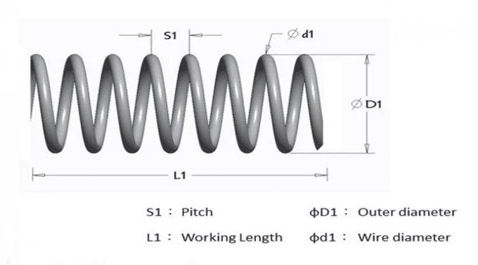
- When coiling straight nichrome heating wire into helical elements, three geometric parameters govern structural stability and heat dissipation:
Winding Ratio (Dcoil / d): A typical engineering guideline for the ratio of outer coil diameter to wire diameter is 4 to 8 (4 <= Dcoil/d <= 8). Ratios under 4 create high mechanical stress during winding; ratios over 8 yield flexible coils that sag easily at high temperatures. - Stretch Ratio & Free Gap (s): Once pulled to installed length, the free air gap (s) between turns should generally measure 1.5 to 3 times the wire diameter (s >= 1.5d). Tightly compressed coils trap radiant heat, driving local wire temperatures well beyond design limits.
- Diameter Tolerances & Electrical Variation: Drawn round wire carries typical commercial diameter tolerances of ±0.01 mm to ±0.02 mm. Because cross-sectional area and resistance scale quadratically (A proportional to d^2), a minor diameter shift can produce a ±3% to ±5% variation in resistance per meter. OEMs should specify target resistance per spool rather than relying solely on drawn dimensional tolerances.
Partner with Hongtai for Precision Heating Wire & Thermal Engineering
Accurate thermal calculations require precision-drawn resistance alloys with consistent metallurgy and tight dimensional tolerances.Hongtai Heater Factory manufactures premium industrial NiCr resistance wire (NiCr 80/20, NiCr 70/30, and NiCr 60/15 round wire, flat ribbon, and pre-coiled helical heating elements). With stringent batch resistance testing, bright-annealed finishes, and high elongation, our products provide dependable thermal performance for element OEMs and industrial furnace builders worldwide.
- Consult our Engineers: Send your wiring schematics to the Hongtai Heater Factory technical team for a free design review.
- Visit Us:: www.hongtai-heater.com
Frequently Asked Questions (FAQ)
Q1: Why is operating hot resistance (R_hot) higher than cold multimeter resistance in Nichrome?
Q2: What is the fastest way to adjust a design if the calculated wire length is too long for the allocated chamber space?
Reduce Wire Diameter (d): A smaller cross-section increases linear resistance (ohm/m), cutting the required length (verify that surface watt loading remains within safe limits).
Switch to Flat Ribbon / Strip: Flat ribbon provides a significantly higher surface-area-to-cross-section ratio than round wire, allowing higher wattage in restricted clearances.
Shift Circuit Architecture: Transition parallel branches into series strings to raise total circuit resistance requirements.