For HVAC project engineers and facility managers, Industrial duct heater sizing & selection and specifying an air duct tubular heater bank requires much more than simply picking a kilowatt rating from a standard catalog. In commercial HVAC and industrial process air heating systems, an improperly sized duct heater frequently leads to nuisance tripping, premature element failure, or unacceptable temperature fluctuations.
Accurate process air heater sizing demands a precise balance between thermodynamic load, air velocity, surface watt density, and control architecture. This engineering guide walks you through the core parameters of a forced air tubular heating system.
1.Duct Heater Design Parameters: CFM, Temperature Rise and Air Properties
Before performing any duct heater CFM calculation, you must establish the fundamental thermodynamic boundary conditions of your system:
- Airflow Volume (CFM – Cubic Feet per Minute): Determines the mass of air passing over the heating elements per unit of time, serving as the baseline for heat load calculations.
- Temperature Rise (ΔT): The differential between the inlet air temperature (T1) and the target discharge temperature (T2), expressed as ΔT = T2 – T1.
- Air Physical Properties: Standard air density is typically evaluated at 0.075 lb/ft³. Variations in altitude, system pressure, and operating temperature directly alter air mass flow.
2.How to Calculate Duct Heater Power in kW
To quickly estimate the required heating capacity, engineers commonly utilize standard shorthand thermodynamic formulas based on standard air properties:
(Note: Depending on specific air density assumptions, some engineering standards utilize conversion factors such as 3160).
- Calculation Example: Consider a system processing 3,000 CFM of air with an inlet temperature of 60°F and a target discharge temperature of 120°F (ΔT = 60°F). Using the 3000 conversion factor:
kW = (3000 × 60) / 3000 = 60 kW
- Operational Boundary (Standard CFM vs. Actual Airflow): This simplified formula is strictly valid only under standard atmospheric conditions. For high-temperature recirculation loops, high altitudes, or pressurized process gases, air density shifts significantly. Final sizing must rely on actual mass flow calculations rather than blind reliance on simplified formulas.
3.Duct Face Velocity and Airflow Distribution
The dynamic behavior of air flowing across the duct cross-section directly dictates convective heat transfer efficiency and equipment longevity.
- Face Velocity Calculation:
Velocity (FPM) = Airflow (CFM) / Duct Area (ft²)
For instance, 3,000 CFM flowing through a 6 ft² duct cross-section yields an average face velocity of 500 FPM (≈ 2.5 m/s), which serves as a helpful preliminary design reference. Actual minimum velocity thresholds depend on element watt density and construction.
- Airflow Uniformity and Hot Spots: Inadequate upstream baffling or diffusers create stagnant airflow zones, resulting in localized high-temperature “hot spots” on the heating element sheaths that accelerate oxidation.
- Pressure Drop and Fan Matching: Denser fin configurations enhance thermal transfer but increase static pressure drop. System selection must verify that the HVAC blower has sufficient static pressure reserve to overcome the heater bank resistance.
4.Element Watt Density and Sheath Temperature
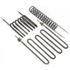
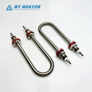
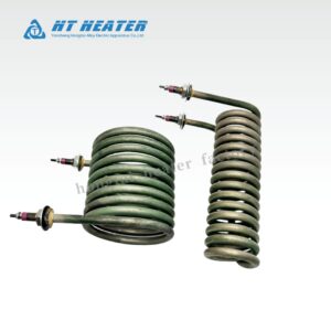
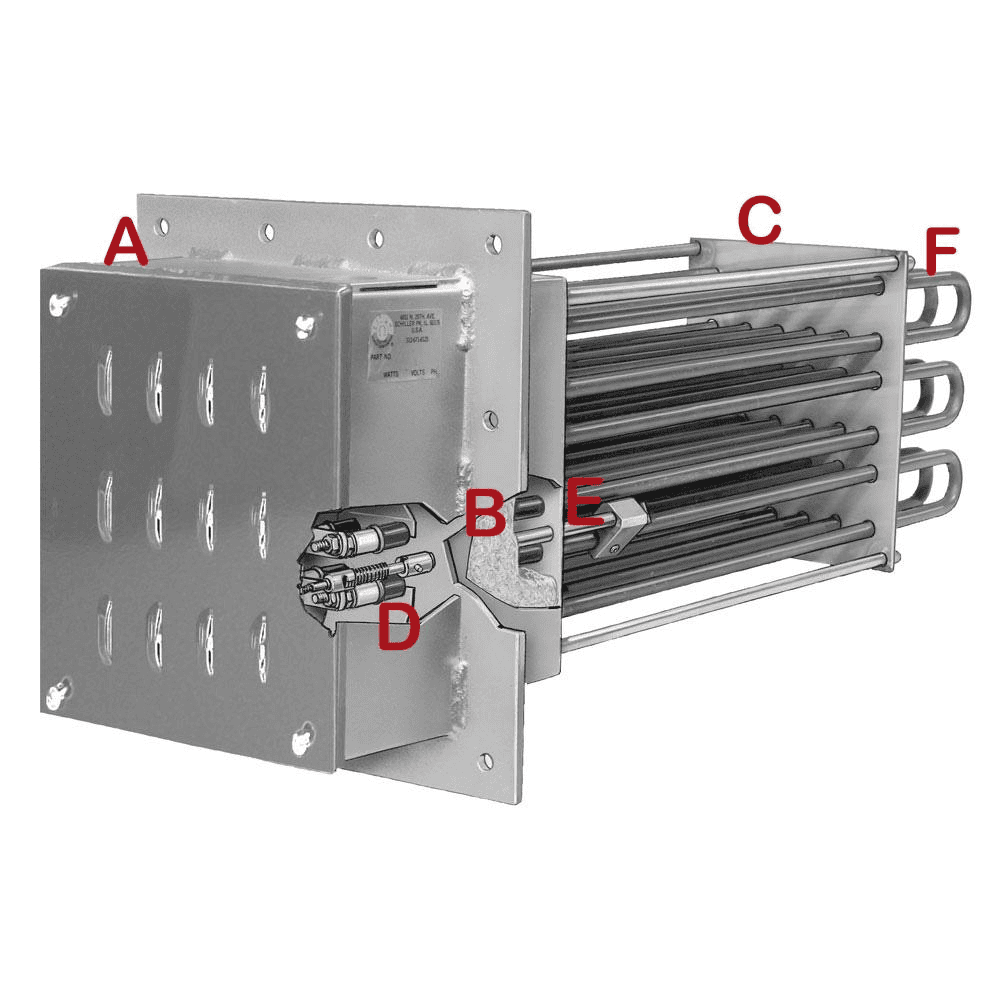
In a forced air tubular heating system, continuous spiral-finned tubular elements (Finned Tubular Heaters) are widely implemented to expand thermal transfer surfaces.
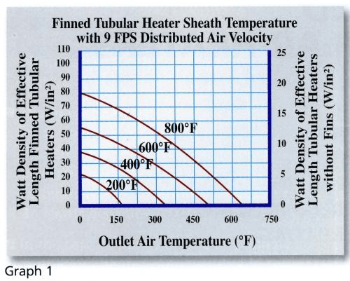
- Element Watt Density:
q” = Power (W) / Surface Area (Ah)
Helical fins expand the effective heat transfer area by 200% to 300%, enabling higher total wattage while keeping surface loading low.
- Sheath Temperature Control: If surface loading is excessive relative to local airflow, sheath wall temperatures will exceed the metallurgical limits of the alloy (e.g., ~650°C for Stainless Steel 304), triggering premature thermal degradation.
5.Staged Control, SSR and SCR Power Regulation
High-capacity duct heater banks require robust electrical control architectures and safety interlocks:
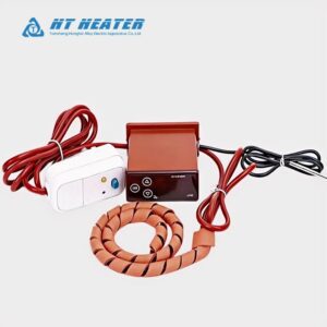
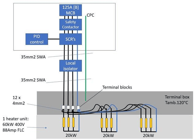
- Capacity Regulation: Options include staged contactor control (e.g., 3 × 20 kW cyclical stepping), SSR solid-state relay staging, or SCR phase-angle/burst-fired power controllers to limit electrical surges and match precise process requirements.
- Safety Interlock Logic:
- Airflow Proving: A differential pressure switch or airflow proving switch must verify that adequate air velocity is established before allowing the heating elements to energize.
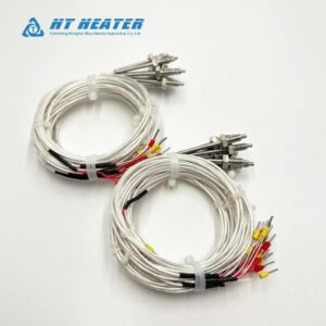
- Dual High-Limit Protection: Systems must incorporate a primary automatic-reset thermal cutout and a secondary manual-reset high-limit switch to cut power during thermal runaways.
6.Custom Duct Heater RFQ Specification Checklist
When submitting an RFQ for custom industrial duct heaters, ensure your engineering specification includes the following parameters:
| Parameter Category | Required Engineering Input |
| Airflow & Media | Rated airflow (CFM or m³/h), altitude/density, max allowable static pressure drop |
| Thermal Profile | Inlet temperature (T1), target discharge temperature (T2), ambient operating range |
| Physical Geometry | Duct inner dimensions, flange connection standards, mounting orientation (horizontal/vertical) |
| Electrical Specs | Supply voltage, phase (1Φ / 3Φ), frequency, total power (kW), number of control steps |
| Control & Safety | Control architecture (Staged/SSR/SCR), airflow proving switch, independent high-limit cutouts |
| Material Standards | Terminal enclosure material, element sheath alloy (SS304/SS316/Incoloy), fin material |
Partner with Hongtai for Engineered Duct Heating Solutions
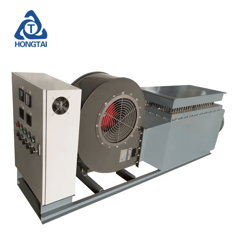
Achieving reliable industrial heating performance requires mastering thermodynamics, fluid mechanics, and electrical safety. Hongtai Heater Factory manufactures custom industrial air duct tubular heater banks engineered precisely to your CFM, kW, and enclosure specifications.
- Consult our Engineers: Send your wiring schematics to the Hongtai Heater Factory technical team for a free design review.
- Visit Us:: www.hongtai-heater.com