Ceramic bobbin heaters provide a modular, high-temperature radiant heating solution for industrial furnace manufacturers and electric heating element design engineers. In controlled-atmosphere heat treatment furnaces, radiant tube assemblies, and large-volume storage tanks, engineering teams must balance high surface heat transfer with electrical insulation integrity and maintenance accessibility. A properly specified ceramic bobbin heater enables rapid element replacement without draining process tanks or shutting down and stripping an entire furnace chamber.
This engineering guide examines the ceramic bobbin body, wound resistance wire, insulation support, and terminal structure, while detailing applicable scenarios, installation conditions, and key differences compared to other furnace heating elements.
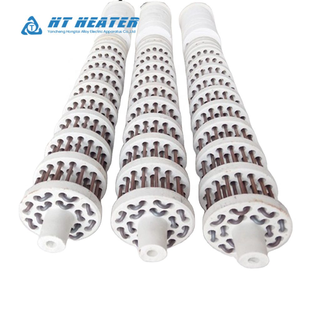
1.Core Construction: Ceramic Bobbins, Resistance Wire & Insulation Support
The mechanical stability and dielectric performance of an industrial ceramic bobbin heating element rely on four integrated sub-assemblies:
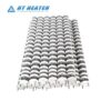
- Refractory Ceramic Bobbins: Constructed from interlocking cylindrical segments of high-purity Steatite, Cordierite, or Mullite/High-Alumina refractory ceramic. Each ceramic section is molded with precision helical grooves or longitudinal channels that cradle the heating coil while providing thermal shock resistance and high-temperature dielectric insulation.
- Wound Resistance Wire: Helically coiled Nickel-Chromium (NiCr 80/20) or Iron-Chromium-Aluminum (FeCrAl) alloy wire is seated along the peripheral grooves of the ceramic body to form an open or semi-enclosed ceramic insulated heating wire array. Because the resistance coil radiates heat directly to the surrounding air or radiant tube wall without a compacted powder barrier, thermal response is immediate. However, surface loading must still be carefully calculated; for detailed thermal loading guidelines, consult Tubular Heater Watt Density: Sizing Guidelines to Prevent Premature Burnout.
- Center Insulation Support and Tie Rod: Individual ceramic bobbins are aligned and compressed along a central high-temperature alloy tie rod (typically Inconel or SS 310S). Heavy-duty ceramic end insulators and expansion compensation springs at the assembly ends absorb axial thermal expansion during furnace cycling, preventing mechanical cracking of the ceramic segments.
- Terminal Structure and Cold Pin Transitions: At the unheated termination end, the resistance wire is welded or crimped to heavy-gauge solid terminal rods (cold pins) that pass through a thermal insulation plug. External connections can be configured with threaded studs, ceramic bead-insulated flexible leads, or terminal blocks. To compare terminal hardware options across high-temperature applications, refer to Tubular Heater Terminations: Threaded Studs, Spade Terminals, and Lead Wires.
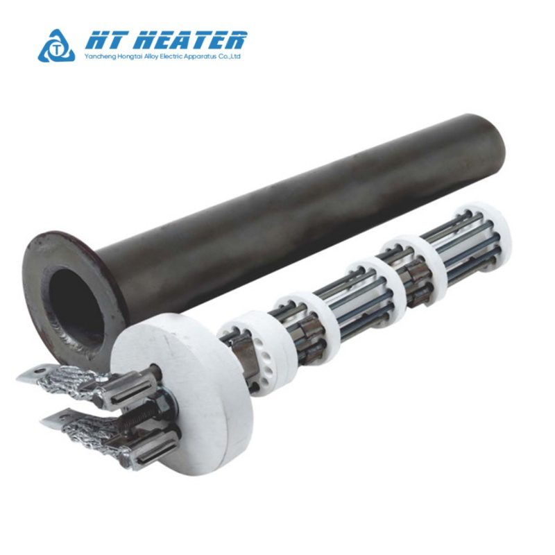
2. How Ceramic Bobbin Heaters Differ from Other Furnace Heating Elements
When specifying thermal components, engineers must distinguish a ceramic bobbin heating element from swaged metal-sheathed tubular heaters and ultra-high-temperature non-metallic furnace elements:
| Engineering Parameter | Ceramic Bobbin Heater | Swaged Metal Tubular Heater | High-Temp Non-Metallic Elements (SiC / MoSi₂) |
|---|---|---|---|
| Insulation & Support | Segmented refractory ceramic bobbins + center tie rod | Metal sheath filled with compacted MgO powder | Self-supporting ceramic or cermet rods/U-elements |
| Resistance Wire State | Open/grooved ceramic insulated heating wire | Fully enclosed inside compressed MgO and metal tube | Element body serves directly as the conductor |
| Primary Heat Transfer | Infrared radiation + natural/forced air convection | Conduction and fluid convection | High-flux thermal radiation |
| Max Element Temp | 1000°C – 1200°C (Alloy & ceramic dependent) | 650°C – 870°C (Sheath limit dependent) | 1500°C – 1800°C+ (Ultra-high-temp kilns) |
| Process Isolation | Installed inside radiant tubes or dry-well pipes | Sheath immerses directly into liquid or gas | Exposed directly to furnace atmosphere |
| Maintenance Access | Replaceable online (Withdraw core without draining tank) | Requires draining vessel for flanged/screw-plug removal | Requires matched-set (SiC) or individual replacement |
- Compared to Swaged Metal Tubular Heaters: Conventional metal tubular elements rely on swaged magnesium oxide (MgO) powder for heat conduction and dielectric isolation (see Inside a Tubular Heater: The Role of Swaged MgO and NiCr Resistance Wire). In viscous or coking fluids, direct-immersion metal sheaths experience rapid surface scaling. By placing a ceramic bobbin heater inside a large-diameter pipe well (thermowell), the external pipe presents a much larger surface area to the fluid, drastically lowering the effective watt density on the liquid side.
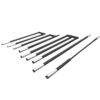
- Compared to Open SiC and MoSi₂ Furnace Elements: For furnace chambers operating above 1300°C, Silicon Carbide (SiC) or Molybdenum Disilicide (MoSi₂) elements are necessary (explore our comparison in Industrial Furnace Heating Elements: NiCr vs. SiC vs. MoSi₂). However, in heat treatment furnaces operating below 1100°C with carburizing or reducing atmospheres, enclosing a furnace bobbin heater inside an alloy radiant tube isolates the resistance wire from corrosive furnace gases while avoiding the expensive current-limiting SCR and multi-tap transformer packages required by SiC and MoSi₂.
3.Applicable Scenarios in Industrial Furnaces and Indirect Heating
Thanks to its radiant heat distribution and withdrawable core architecture, the ceramic bobbin heater is widely deployed across three primary industrial applications:
- Industrial Furnace Radiant Tube Heating: Installed inside sealed heat-resistant alloy or ceramic radiant tubes as a primary furnace bobbin heater. In carburizing, nitriding, annealing, and tempering furnaces, the outer radiant tube prevents protective or high-carbon atmospheres from attacking the heating wire, while allowing maintenance teams to pull and swap a failed ceramic core while the furnace remains hot.
- Indirect Tank & Dry-Well Pipe Heating: Inserted into blind steel or stainless steel pipes welded into the base of large storage tanks. This configuration heats heavy fuel oil, bitumen, asphalt, wax, molasses, or corrosive chemical baths without direct element-to-liquid contact. Where direct immersion is still preferred over dry-wells, engineers can compare mounting configurations in Flanged vs. Screw Plug Immersion Heaters: Mounting & Pressure Selection Guide.
- Industrial Ovens, Salt Baths & Galvanizing Kettles: Mounted in banks around the perimeter of galvanizing kettles, salt bath furnaces, or high-temperature drying ovens to deliver uniform radiant heat without localized overheating.
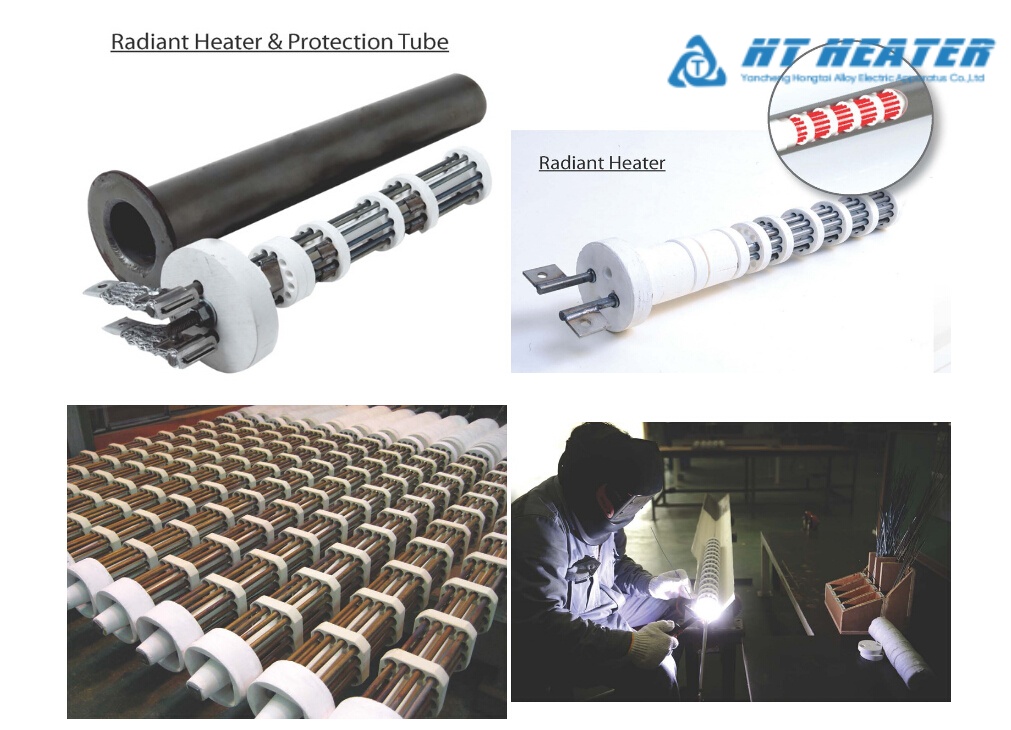
4.Installation Conditions and Engineering Design Rules
To prevent premature coil shorting, ceramic fracture, or terminal burnout, engineers must enforce strict installation conditions when integrating a ceramic bobbin heating element:
- Horizontal vs. Vertical Mounting Orientation: Standard ceramic bobbin heaters are engineered for horizontal installation inside radiant tubes. When an application requires vertical installation (such as vertical pit furnaces or top-mounted radiant tubes), gravity can cause the softened high-temperature resistance coil to sag and slip out of standard shallow grooves, causing turn-to-turn short circuits. Vertical installations must be explicitly specified so the factory can utilize deep-groove interlocking bobbins, ceramic retaining pins, or segmented support collars to lock the ceramic insulated heating wire in place.
- Radiant Tube ID Clearance: Maintain a radial clearance of 1.5 mm to 3.0 mm (or 3 mm to 6 mm total diameter differential) between the ceramic bobbin outer diameter (OD) and the radiant tube inner diameter (ID). Insufficient clearance risks jamming the ceramic assembly if the metal radiant tube warps at high temperatures, whereas excessive clearance increases radiative thermal resistance and drives up wire operating temperature.
- Surface Watt Density Limits: Because heat dissipates primarily via radiation inside an enclosed tube, element surface watt density is typically engineered between 1.5 W/cm² and 4.5 W/cm² depending on chamber temperature and tube alloy.
- Cold Zone and Terminal Isolation: The unheated cold pin section must extend completely through the furnace refractory wall or tank flange neck so that external connections remain within safe ambient temperature thresholds. Furthermore, because the resistance wire is unsealed, ceramic bobbin elements must never be exposed to conductive dust, condensing moisture, or direct liquid splashes (for failure analysis on insulation breakdown, see Troubleshooting Tubular Heaters: Sheath Rupture, Scaling, and Current Leakage).
5.Custom Ceramic Bobbin Heater RFQ Specification Checklist
When submitting a custom design inquiry to Hongtai Heater Factory, providing a complete engineering dataset accelerates DFM review and prototyping (for general drawing guidelines, see How to Specify Custom OEM Tubular Heaters for B2B Procurement):
| Parameter Category | Required Engineering Input |
|---|---|
| Geometric Dimensions | Ceramic bobbin OD (e.g., 28 mm – 150 mm), overall length, heated length, and cold zone length |
| Radiant Tube / Well Specs | Host pipe inner diameter (ID), wall thickness, tube material (see Sheath Materials for Tubular Heaters: Incoloy, Stainless Steel & Titanium), and operating temp |
| Electrical Specifications | Supply voltage, rated wattage (kW), phase configuration (1-phase or 3-phase Star/Delta), and target watt density |
| Material Selection | Ceramic grade (Steatite, Cordierite, or High-Alumina) and resistance wire alloy (NiCr 80/20 or FeCrAl) |
| Mounting & Termination | Horizontal or vertical orientation, mounting flange/insulation plug dimensions, and terminal style |
Partner with Hongtai for Engineered Ceramic Bobbin Heating Solutions
Achieving uniform radiant heat distribution and long-term furnace reliability requires mastering refractory ceramic dielectrics, resistance alloy metallurgy, and radiant tube clearance tolerances.Hongtai Heater Factory manufactures custom industrial ceramic bobbin heaters and furnace bobbin heater assemblies engineered precisely to your radiant tube ID, watt density, and mounting orientation specifications.
- Consult our Engineers: Send your wiring schematics to the Hongtai Heater Factory technical team for a free design review.
- Visit Us:: www.hongtai-heater.com