The Scenario: You install a high-precision Class A Pt100 sensor. You run 50 meters of cable back to the control room. You power it up, and the controller reads 23°C, even though you know the tank is at 20°C. You replace the sensor, but the error remains.
The Physics: The problem isn’t the sensor. It is the wire. Copper wire is a resistor. A standard Pt100 sensor changes resistance by roughly 0.385 Ω for every degree Celsius. If your 50-meter cable adds just 1.2 Ω of resistance to the circuit, your controller interprets that as an extra 3°C of heat.
That $500 worth of precision instrumentation has been rendered useless by a spool of wire.
This guide analyzes the Wheatstone Bridge principles behind RTD wiring. We will explain why 3-Wire is the undisputed king of industry, why 2-Wire is dangerous, and when you must upgrade to the laboratory gold standard of 4-Wire.
The 2-wire configuration is the simplest, and unfortunately, the most inaccurate method of temperature measurement.
The Problem
The controller measures the Total Resistance (R_T) of the loop.
R{Measured} = R{Lead 1} + R_{Sensor} + R_{Lead 2}
The controller has no way of knowing which part of that resistance is the platinum sensor and which part is the copper wire. It blindly adds them together, resulting in a reading that is always higher than the actual temperature.
When to Use It?
Only use 2-wire RTDs if:
Short Distance: The wire is < 1 meter (e.g., inside an enclosure).
Low Accuracy: You are doing HVAC work where ±2°C is acceptable.
High Resistance Sensors: You are using a Pt1000. Since a Pt1000 changes 3.85 Ω/°C, the error caused by the wire is diluted by a factor of 10, making it negligible for short runs.
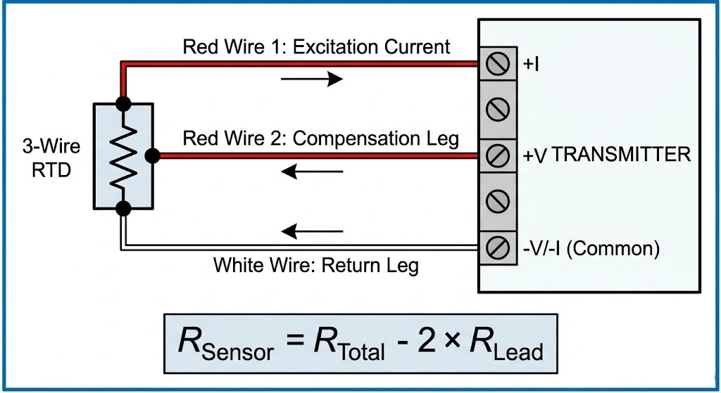
3-Wire Connection: The Industry Standard
This is the configuration you will see in 90% of industrial process control applications (Refineries, Power Plants, Factories).
The Magic of the “Third Wire”
To solve the wire resistance problem, we add a third wire to one side of the sensor. In a standard color code (IEC), you will see 2 Red wires and 1 White wire.
The two Red wires are internally shorted at the probe tip.
How It Works (The Math)
The controller uses a Wheatstone Bridge circuit to perform two measurements:
Loop A: Measures Resistance of (Lead 1 + Lead 2). Since Lead 1 and Lead 2 are connected at the tip, this gives the controller the value of just the wire.
Loop B: Measures Resistance of (Lead 2 + Sensor + Lead 3).
The Calculation:R_{Sensor} = R_{Loop B} – R_{Loop A}
(Assuming R_{Lead 1} = R_{Lead 2} = R_{Lead 3}
The Critical Requirement
For this math to work, all three wires must be identical. They must be the same length, same gauge (AWG), and same material. If you splice a thinner wire into just one leg of the circuit, you break the balance, and the compensation fails.
When accuracy is non-negotiable (e.g., Custody Transfer or Calibration Labs), we use 4-Wire.
Concept: Kelvin Sensing
This method separates the Current path from the Voltage measurement path.
Wires 1 & 4 (Source): Carry the constant current to excite the sensor.
Wires 2 & 3 (Sense): Measure the voltage drop across the sensor element.
Why It Is Perfect
A voltmeter has infinite input impedance. This means zero current flows through the Sense wires.
V = I *R
If Current (I) is zero, then the Voltage drop (V) across the lead wire is zero. The lead resistance is completely ignored. You could run 1,000 meters of thin wire, and the reading would still be dead accurate.
Calculation Demo: The Cost of Being Wrong
Let’s quantify the error with a real-world example.
Scenario: A Pt100 sensor with 100 feet (30 meters) of 24 AWG Copper Extension wire.
Wire Resistance: ~1.6 Ω total loop resistance.
Pt100 Sensitivity: ~0.385 Ω/°C.
The Error Calculation:
1.6 Ω ÷ 0.385 Ω/°C ≈ 4.15 ℃ Error
Verdict: If you connect this as a 2-wire circuit, your expensive Class A sensor (rated for ±0.15°C) is now reading 4°C too high. You have turned a precision instrument into a guessing stick. You must use 3-wire or 4-wire compensation.
The Modern Alternative: Head-Mounted Transmitters
What if you have to run a signal 500 meters across a noisy factory? Even a 3-wire analog signal acts as an antenna for EMI (Electromagnetic Interference).
The Solution: Use a Head-Mounted 4-20mA Transmitter.
This small “puck” fits inside the sensor connection head. It converts the fragile resistance signal into a robust Current Loop.
Benefit: Current does not fade over distance. The signal at 1 meter is identical to the signal at 500 meters.
Wiring: You only need 2 copper wires for the long run back to the PLC, and they carry both power and signal.
Comparison Summary Table
Use this table to decide which configuration fits your budget and accuracy needs.
Type
Accuracy
Lead Wire Compensation
Max Distance
Typical Application
2-Wire
Poor
None
< 1 meter
HVAC, Pt1000, Short Patch Cables
3-Wire
Good
Calculated (assumes balanced wires)
< 100 meters
Industry Standard (Refining, Mfg, Food)
4-Wire
Excellent
True Elimination (Kelvin)
< 100 meters
Metrology Labs, Calibration Standards
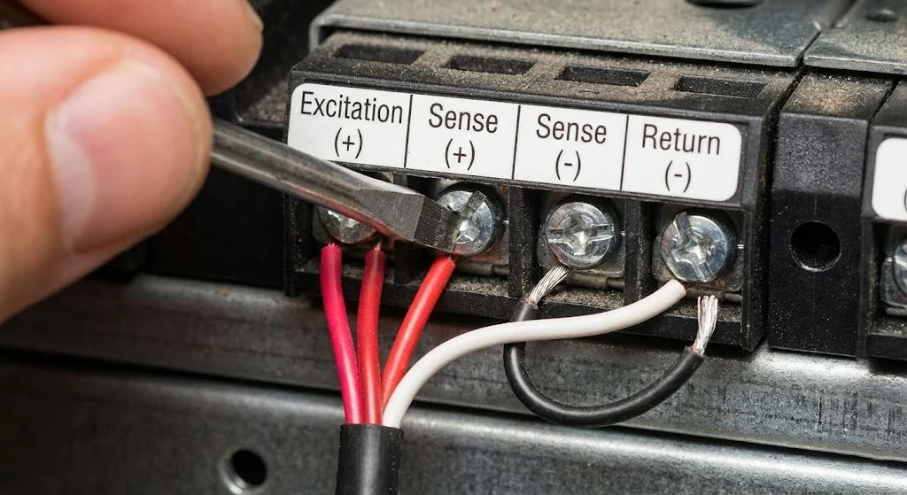
Connecting 3-wire RTD to PLC terminal block wiring example.
Frequently Asked Questions (FAQ)
Why do RTDs have 3 wires?
The third wire is used to compensate for the electrical resistance of the long lead wires. In an industrial environment, cables add “phantom resistance” that the controller would otherwise interpret as temperature. The 3-wire Wheatstone Bridge circuit allows the controller to measure the wire resistance separately and subtract it from the total reading.
Can I connect a 3-wire RTD to a 2-wire input?
Yes, but you will lose accuracy. To do this, you connect the two common color wires (usually the two Reds in IEC standard) together into one terminal. However, the resistance of your extension wire will now be added to your reading, causing a positive temperature offset.
What is the difference between Pt100 and Pt1000 wiring?
The wiring principles (2, 3, or 4 wire) are the same, but a Pt1000 sensor is much less sensitive to lead resistance errors. Because a Pt1000 has a base resistance of 1000 , a 1 wire error represents a much smaller percentage of the signal compared to a Pt100. This makes 2-wire connections acceptable for many Pt1000 applications.
How do I test a 3-wire RTD with a multimeter?
1.Measure resistance between the two same-colored wires (e.g., Red-Red); it should be close to 0 Ω (continuity). 2.Measure between the odd-colored wire (White) and either Red wire; it should be around 100 Ω (at room temperature). 3.If any reading is “OL” (Infinite), the sensor or wire is broken.