The Phenomenon: You press the control knob on a gas heater, and the pilot lights up instantly. You hold it for ten seconds, but the moment you release your thumb, the flame dies.
The Physics: This is not a mechanical failure. It is a Thermoelectric Safety Loop functioning exactly as designed. The system “thinks” there is no fire, so it cuts the fuel supply to prevent your facility from filling with combustible gas.
At the heart of this system lies a $5 copper component that acts as the primary defense against explosion: the Thermocouple Flame Sensor.
While often viewed as a simple repair part, this sensor is a marvel of “Millivolt Physics.” It operates without external power, generating its own electricity to hold open a spring-loaded safety valve. This guide digs into the engineering principles behind the 30mV loop, helps engineers distinguish between Thermocouples and Flame Rectification Rods, and provides a forensic troubleshooting SOP.
To understand why these sensors fail, you must understand the battle happening inside the gas valve. It is a contest between Magnetism and Elasticity.
The Seebeck Effect in Action
The pilot thermocouple consists of two dissimilar metals (usually a Chromel outer sheath and a constantan inner conductor) joined at the tip. When the pilot flame heats this tip to 600-800°C, while the base remains cool, the temperature differential generates a DC voltage of approximately 25mV to 30mV.
The Battle: Electromagnet vs. Spring
Inside the gas safety valve, there is a powerful spring pushing a rubber seal shut.
Manual Start: When you push the knob, you physically overcome the spring force and push the valve open. Gas flows, and you light the pilot.
Power Generation: As the thermocouple heats up, that 30mV current flows through a copper winding (electromagnet) inside the valve.
The Hold: The electromagnet becomes energized and creates just enough magnetic force to hold the valve open against the spring pressure.
Fail-Safe: If the pilot blows out, the tip cools. The voltage drops to zero. The magnet loses power. The spring snaps the valve shut. Gas Off.
Thermocouple vs. Flame Rectification Rod
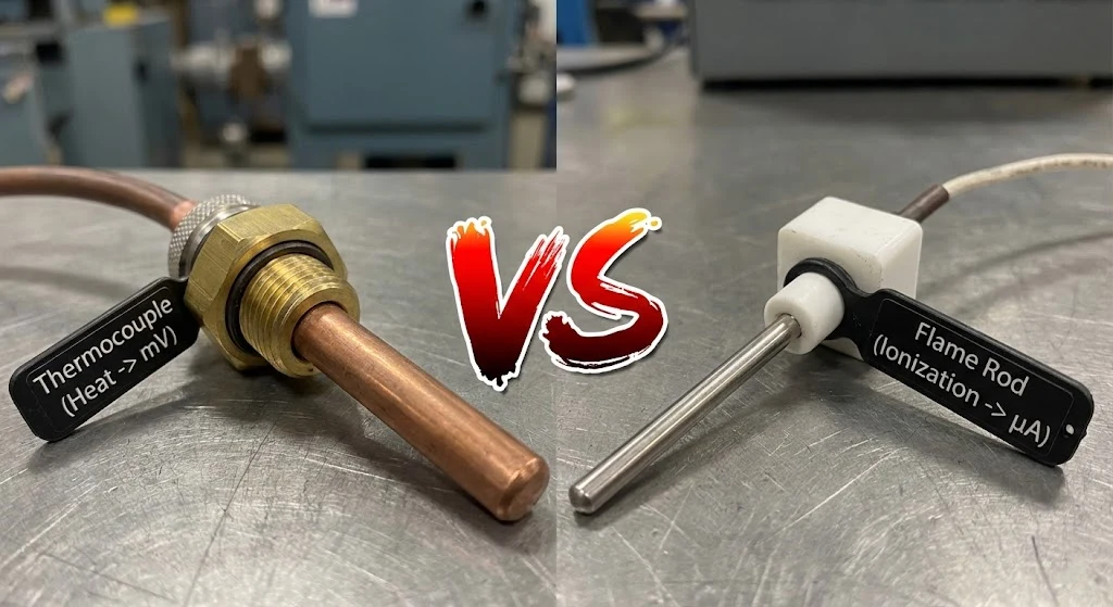
This is the most common point of confusion for procurement managers and junior technicians. Both are called “Flame Sensors,” but they operate on entirely different principles and are not interchangeable.
Type A: The Thermocouple (2-Wire / Coaxial)
Principle:Heat Generation. It creates its own DC electricity.
Appearance: A thick, rigid copper tube (which is actually a coaxial lead wire). It screws directly into the gas valve.
Application: Older standing-pilot boilers, gas fireplaces, commercial water heaters, and fryers.
Signal: 30 millivolts DC.
Type B: The Flame Rod (1-Wire)
Principle:Flame Rectification (Ionization). It relies on the fact that a flame plasma can conduct electricity. The control board sends an AC voltage to the rod; the flame “rectifies” it into a pulsating DC current which flows to the ground.
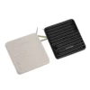
Appearance: A thin metal rod (Kanthal) partially encased in a white ceramic insulator. It has a single spade terminal for a wire connection.
Application: Modern high-efficiency furnaces, electronic ignition systems, and smart HVAC units.
Signal: 2-10 microamps ($\mu A$).
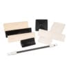
Difference between thermocouple and flame rectification sensor visual comparison.
Troubleshooting: Why Good Sensors “Fail”
When a system fails the safety check, don’t rush to replace the sensor. 50% of “failed” thermocouples are simply dirty or poorly installed.
Carbon Build-up (The Insulator)
Incomplete combustion leaves soot (Carbon) on the probe tip. Carbon is a thermal insulator. It acts like a blanket, preventing the flame heat from reaching the alloy junction.
Symptom: Voltage drifts down to 10-12mV, which is too weak to hold the magnet.
The Fix: Clean the probe with a Scotch-Brite pad or very fine steel wool.
Engineering Warning:NEVER use coarse sandpaper. Sandpaper leaves deep scratches. These micro-grooves trap more carbon and increase surface area for oxidation, causing the sensor to fail again within weeks.
The “Cold Junction” Problem
Thermocouples rely on $\Delta T$ (Temperature Difference). Voltage = (Hot Tip Temp) – (Cold Base Temp).
The Issue: If the entire burner chamber is poorly ventilated and overheats, the “Cold Junction” at the base of the probe gets hot. The $\Delta T$ shrinks, and the voltage drops—even if the pilot is roaring.
The Fix: Ensure the pilot assembly has proper airflow cooling the base of the sensor.
The Multimeter Test: Is it the Sensor or the Valve? (SOP)
HVAC technicians often guess. Engineers measure. Here is the Standard Operating Procedure (SOP) to isolate the fault.
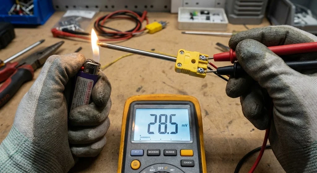
Step 1: Open Circuit Test (The Health Check)
Disconnect the thermocouple from the gas valve.
Light the pilot (hold the knob in manually).
Attach multimeter leads: One to the copper sheath (Ground), one to the tip of the connector (Positive).
Target:25mV to 30mV within 45 seconds.
Diagnosis: If reading is < 15mV, the sensor is dead (degraded junction). Replace it.
Step 2: Closed Circuit / Load Test (The Stress Test)
A sensor might show 30mV unloaded but fail under load due to internal high resistance.
Use a thermocouple adapter to connect the multimeter in series between the sensor and the valve.
Light the pilot and let the knob go.
Target: The voltage should stabilize above 12mV.
Diagnosis:
High Voltage (25mV) but Valve Drops: The sensor is fine. The Gas Valve Electromagnet is defective.
Low Voltage (<10mV): The sensor has high internal resistance. Replace the sensor.
Testing gas fireplace thermocouple voltage with a multimeter.
For OEMs: Designing Reliable Pilot Assemblies
If you are a manufacturer designing a gas appliance, the placement of the thermocouple is critical for warranty reduction.
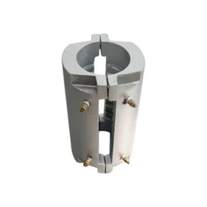
Mounting Brackets Matter
The pilot flame should impinge on the top 1/3 to 1/2 of the thermocouple tip.
Too Low: If the flame heats the base (cold junction), voltage output drops.
Too High: If only the very tip touches the flame, there isn’t enough thermal mass to maintain the signal during flame flicker (drafts).
Fast Response Thermocouples
For safety certification, the “Dropout Time” (time from flameout to gas cut-off) is critical.
Recommendation: Specify thermocouples with a “Fast Dropout” characteristic (typically 30-60 seconds). This ensures that if the wind blows out the pilot, the room doesn’t fill with gas for 3 minutes before the valve shuts.
Replacement Guide: Universal vs. OEM Specific
Universal Kits: These are designed for service vans. They come with a 30-inch lead and a bag of 5-6 different threaded adapters/clips to fit various valves. Great for emergency repair, but higher unit cost.
OEM Custom: For factory production, “Universal” is waste. We manufacture the exact length (e.g., 18-inch) with the specific termination (Coaxial, Spade, or Split-Nut) required for your valve. This eliminates the cost of adapters and reduces assembly time.
Frequently Asked Questions (FAQ)
How do I know if my flame sensor is bad?
If the pilot lights but goes out immediately when you release the control knob, the sensor is the prime suspect. First, try cleaning the probe tip. If cleaning fails, test the voltage with a multimeter. An open-circuit reading below 15mV usually confirms the sensor junction has degraded and must be replaced.
Can I bypass a flame sensor?
Absolutely NEVER. Bypassing the flame sensor disables the safety shut-off mechanism. If the flame goes out for any reason (wind, blockage), gas will continue to pump into the room. This creates a massive explosion hazard. Always replace, never bypass.
What is the difference between a thermocouple and a thermopile?
A thermocouple is a single junction generating ~30mV, enough to hold a small pilot valve open. A thermopile is a stack of multiple thermocouples (10 to 30) wired in series within a single probe. It generates a higher voltage (500mV – 750mV), which is powerful enough to operate the main gas valve and a thermostat without any external electricity.
How do you clean a thermocouple flame sensor?
Use a dollar bill, a coarse cloth, a Scotch-Brite scouring pad, or very fine steel wool. Avoid coarse sandpaper. Sandpaper creates deep micro-scratches on the metal surface. These scratches trap carbon soot and promote oxidation, causing the sensor to fail again much faster.