In 99% of electrical engineering, Red means Positive (+). It is the universal language of DC power.
In the world of American (ANSI) thermocouples, Red is Negative (-).
This single counter-intuitive fact is responsible for thousands of hours of downtime and catastrophic equipment failures every year.
The Scenario: A field technician wires a Type K thermocouple into a PID controller, following standard electrical logic: Red to Positive (+).
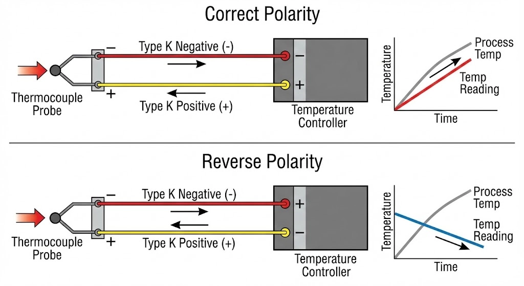
The Consequence: As the furnace heats up, the controller receives a reverse polarity signal. The temperature reading on the display drops instead of rises. The PID algorithm thinks the process is freezing, so it commands the heater to fire at 100% output.
The Result: Thermal runaway. The heaters melt, the product is ruined, or in the worst case—explosion.
This guide is your “Field Survival Manual.” We are not just listing colors; we are providing the “Anti-Error” logic to identify sensors even when the insulation is burned off or the standards are mixed. Bookmark this page—it might save your machine.
Unsure which thermocouple type you are actually looking at? Check our Industrial Sensor Selection Guide to identify the probe first.
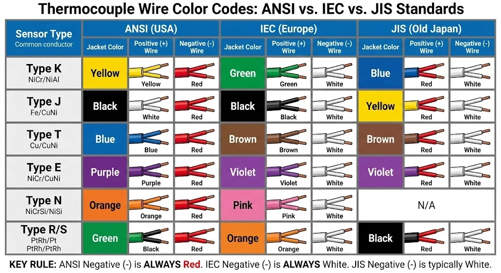
The “Big Three” Standards: ANSI vs. IEC vs. JIS
Global manufacturing means you will encounter sensors from everywhere. A machine built in Germany (IEC) will have different wiring than a machine built in Ohio (ANSI) or a legacy machine from Osaka (JIS).
1. ANSI (United States) – ASTM E230
The Rule: The Negative (-) wire is ALWAYS RED.
The Positive (+) wire adopts the color of the thermocouple type (Yellow for K, White for J).
Mnemonic: “Red is Red-Hot? No. Red is Negative.”
2. IEC (Europe/International) – IEC 60584-3
The Rule: The Negative (-) wire is ALWAYS WHITE.
The Positive (+) wire adopts the color of the thermocouple type (Green for K, Black for J).
The Jacket: Usually matches the Positive wire color.
Confusion Point: If you see a White wire, is it an ANSI Type J Positive, or an IEC Negative? You must check the other wire color to confirm.
3. JIS (Japan) – JIS C 1610
The Trap: Japan updated their standards in 1995 to align closer to IEC, but thousands of “Pre-1995” machines are still running.
Legacy JIS: Used Blue for Type K positive and Yellow for Type J positive. If you are servicing an old Toshiba or Fanuc injection molding machine, watch out for this.
The Ultimate Color Code Lookup Table
Use this matrix to identify your wire immediately.
Type
Standard
Jacket Color
Positive (+) Wire
Negative (-) Wire
Type K
ANSI (USA)
🟨 Yellow
🟨 Yellow
🟥 Red
Type K
IEC (EU)
🟩 Green
🟩 Green
⬜ White
Type K
JIS (Old)
🔵 Blue
🔵 Blue
⬜ White
Type J
ANSI (USA)
⬛ Black
⬜ White
🟥 Red
Type J
IEC (EU)
⬛ Black
⬛ Black
⬜ White
Type J
JIS (Old)
🟨 Yellow
🟨 Yellow
🔵 Blue
Type T
ANSI (USA)
🔵 Blue
🔵 Blue
🟥 Red
Type T
IEC (EU)
🟫 Brown
🟫 Brown
⬜ White
Type E
ANSI (USA)
🟣 Purple
🟣 Purple
🟥 Red
Type E
IEC (EU)
🟣 Violet
🟣 Violet
⬜ White
Type N
ANSI (USA)
🟧 Orange
🟧 Orange
🟥 Red
Type N
IEC (EU)
🩷 Pink
🩷 Pink
⬜ White
Pro Tip:Type N is becoming the standard for high-temp applications. Note the distinct Orange (ANSI) vs Pink (IEC) jackets.
Comprehensive Thermocouple Color Code Chart ANSI IEC JIS Standards.
No Colors? No Problem. Identifying Polarity Physically
Field Scenario: You open a connection head. The heat has cooked the wire insulation into a brittle, black mess. The colors are gone. How do you wire it without guessing?
You use physics.
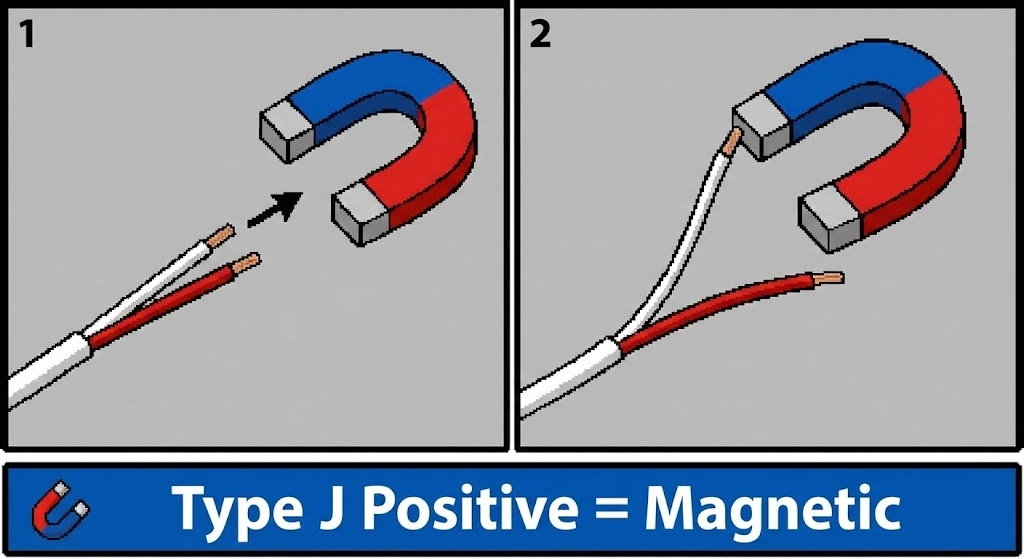
1. The Magnet Test (Type K vs Type J)
You should always carry a small magnet in your tool bag.
Type J (Iron / Constantan):
Positive Leg (+): Made of Iron. Strongly Magnetic.
Negative Leg (-): Constantan. Non-magnetic.
Test: If the magnet picks up the positive wire firmly, it is Type J.
Type K (Chromel / Alumel):
Negative Leg (-): Alumel. Slightly Magnetic.
Positive Leg (+): Chromel. Non-magnetic.
Test: If the magnet has a weak attraction to the negative wire, it is Type K.
Magnetic test to identify Type J thermocouple polarity.
2. The Hardness/Sheen Test
If you have a keen eye, the metal alloys themselves look different.
Type T: The Positive (+) leg is pure Copper. It looks like standard electrical wire (reddish-gold). The Negative (-) leg is Constantan (silver-grey).
Type K: The Positive leg (Chromel) is typically non-shiny and dull. The Negative leg (Alumel) is often shinier.
Extension Wire vs. Compensating Cable
Not all thermocouple wires are created equal. You will often see a letter code on the wire jacket, like “KX” or “KC”.
“X” vs “C” Grades
Extension Grade (e.g., KX, JX): The wire is made of the exact same alloy as the sensor probe. It has high accuracy and can withstand higher temperatures.
Compensating Grade (e.g., KC, KCA): The wire is made of cheaper copper alloys that mimic the EMF output of the thermocouple, but only at ambient temperatures (usually < 100°C).
Risk: If the connection point gets too hot, Compensating cable will introduce massive errors.
The “Copper Wire” Mistake
Never extend a thermocouple signal using standard copper electrical wire.
The Physics: Creating a connection between a thermocouple alloy (e.g., Chromel) and Copper creates a Parasitic Junction.
The Result: Your controller will measure the temperature at the splice point, not the probe tip. If you must run copper, you must use a transmitter to convert the signal to 4-20mA first.
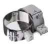
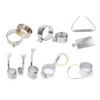
Connector & Plug Standardization
The plastic connectors (plugs) also tell a story.
Pin Sizes: Standard vs. Mini
Standard (Round Pins): Used in heavy industry, panels, and rugged environments. High current capacity (though TCs don’t carry current, the plugs are robust).
Mini (Flat Pins): Used for handheld meters and lab equipment.
Plastic Body Colors
The plastic body of the connector almost always follows the ANSI color standard, even if the wire inside is IEC.
Yellow Body: Type K
Black Body: Type J
Blue Body: Type T
Image Alt Text: Thermocouple reverse polarity wiring diagram and temperature error graph.
Frequently Asked Questions (FAQ)
Which wire is positive on a Type K thermocouple?
In the USA (ANSI standard), the Yellow wire is Positive and the Red wire is Negative. In Europe (IEC standard), the Green wire is Positive and the White wire is Negative. Always verify which standard your equipment uses before terminating.
Why is the red wire negative on thermocouples?
This is specific to the American ANSI/ASTM standard. While the origin is historical, a helpful mnemonic for engineers is: “Red” stands for “Red-hot”, but in electricity, you must stop and think—so Red is the warning color for Negative in thermocouple circuits.
What happens if you wire a thermocouple backwards?
The temperature reading will move in the opposite direction. As the process heats up, the controller will read a dropping temperature (e.g., room temperature minus the heat rise). This causes the PID controller to increase power continuously, leading to potential overheating and system failure.
How can I identify a thermocouple type without color codes?
Use a magnet. For Type J, the positive wire (Iron) is strongly magnetic. For Type K, the negative wire (Alumel) is slightly magnetic. Type T is easy to identify because the positive leg is copper-colored.