In the industrial manufacturing sector, thermal inefficiency is a silent profit killer. A heater failure doesn’t just cost the price of a replacement part; it costs hours of production downtime. For engineers and procurement managers, the challenge in 2026 isn’t just buying a heater—it’s specifying a thermal solution that matches the exact hydrodynamic and thermodynamic conditions of the application.
This guide goes beyond the basic catalog data. It explores the physics of heat transfer, the material science behind sheath selection, and the critical calculations required to prevent premature element failure.
1. Anatomy of Failure: Why Heaters Burn Out
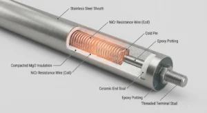
To specify a better heater, one must understand why they fail. A tubular heater is a simple device—a resistance wire inside a metal tube—but its longevity relies on three internal engineering factors often overlooked in standard spec sheets.
The Role of MgO Compaction (Dielectric Strength)
The insulation material, Magnesium Oxide (MgO), serves two conflicting purposes: it must conduct heat away from the wire but block electricity.
-
The Engineering Reality: If the MgO powder is not compacted to a specific density (rock-hard), air pockets remain. Air is a thermal insulator. These pockets cause “hot spots” on the resistance wire, leading to internal melting.
-
The Spec: High-quality elements utilize high purity magnesium oxide powder compacted to maximize heat conductivity and dielectric strength.
The Cold Pin Junction
A common failure point is the terminal. If the resistance wire extends too close to the terminal, the heat melts the wiring insulation.
-
The Solution: Professional-grade heaters employ an integral cold pin fusion welded to the helical resistance wire. This “Cold Zone” ensures that the heat generation stops well before the terminal, maintaining a safe temperature for electrical connections.
2. The Physics of Selection: Watt Density Calculation
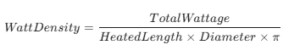
The most critical specification you will write is Watt Density (Watts per Square Inch). It determines the intensity of the heat transfer.
The Golden Rule: The more viscous (thick) or stagnant the medium, the lower the Watt Density must be.
How to Calculate Watt Density
Before ordering, verify your design with this formula:
Industry Guidelines for 2026:
-
Water (Moving): High heat transfer allows for 60-100 W/in².
-
Oil (Lube/Hydraulic): Poor heat transfer. Exceeding 20-30 W/in² causes the oil to carbonize (coke) on the sheath, acting as an insulator and causing the heater to overheat.
-
Air (Static): Must be kept low (10-20 W/in²) to prevent sheath oxidation.
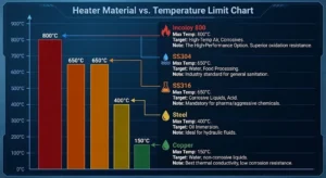
3. Material Science: Incoloy vs. Stainless Steel
Choosing the sheath material is not about cost; it is about chemical compatibility. Using the wrong alloy accounts for nearly 40% of corrosion-related leaks.
Refer to this engineering standard table for your selection:
| Material | Max Temp | Target Application | Engineering Note |
| Copper | 150°C |
Water, non-corrosive liquids |
Best thermal conductivity but low corrosion resistance. |
| Steel | 400°C |
Oil immersion |
Ideal for hydraulic fluids; prevents reaction with oil. |
| SS304 | 650°C |
Water, Food Processin |
The industry standard for general sanitation and heating. |
| SS316 | 650°C |
Corrosive Liquids, Acid |
Mandatory for pharmaceutical or aggressive chemical tanks. |
| Incoloy 800 | 800°C |
High-Temp Air, Corrosives |
The High-Performance Option. Superior oxidation resistance for radiant heating. |
[check our Incoloy 800 specifications]
4. Voltage & Termination: The Connection Criticality
The interface between the heating element and your power source is often the weakest link. In 2026, safety regulations demand robust connection points that prevent arcing and overheating.
Termination Technology
A loose connection creates resistance, which generates heat outside the element, melting wire insulation.
-
Ceramic & Mica Insulation: We utilize threaded screw terminals with ceramic or mica insulators. Unlike standard plastic connectors, these materials withstand high localized temperatures and provide a positive, vibration-resistant connection from lead wire to terminals.
-
Integral Cold Pin: As mentioned in the anatomy section, the internal cold pin is fusion-welded to the resistance wire. This ensures the terminal itself stays relatively cool, protecting your wiring harness.
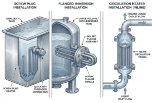
Installation & Mounting Styles
We adapt the termination hardware to your tank or air duct design:
-
Screw Plug: Ideal for smaller tanks and quick installation.
-
Flanged Immersion: For high-pressure or large-volume industrial tanks.
-
Circulation Heaters: For inline heating of flowing liquids.
5. Engineering Specifications & Sizing Calculation
Precision is non-negotiable. Below are the manufacturing limits and the formula to verify your power requirements.
Dimensional Capabilities
We manufacture elements to precise tolerances to fit milled grooves or existing machinery:
-
Diameter Range: From 6.00mm to 25.00mm (±0.15mm tolerance).
-
Max Length: Up to 6000mm for smaller diameters and 7000mm for diameters ≥14mm.
Electrical Tolerances (ASTM Standard)
To ensure safety and grid compliance:
-
Voltage: Custom wound up to a maximum of 550V.
-
Wattage Tolerance: +5% / -10%.
- Resistance Tolerance: +10% / -5%.
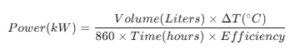
📐 How to Size Your Heater: The Formula
Don’t guess the wattage. Use this simplified thermal calculation to determine the required power (kW) for your application.
-
△T(Temperature Rise): Target Temp – Start Temp.
-
Efficiency: Typically 0.9 (90%) for immersion heaters, 0.5 (50%) for radiant air heating.
-
860: Constant conversion factor (kcal/h to kW).
Engineer’s Tip: Always add a 20% safety margin to your final result to account for voltage fluctuations and heat loss through tank walls.
6. Case Study: The Retrofit Challenge
The Scenario: A food processing facility faced repeated heater failures in their vegetable oil fryer. The OEM heaters (SS304) were failing every 3 months.
The Root Cause Analysis: The engineers discovered the heaters had a Watt Density of 45 W/in². While acceptable for water, this was too high for oil, causing carbon buildup (coking) that suffocated the heater.
The Engineered Solution:
-
Material Upgrade: Switched to Steel sheath to reduce chemical reactivity with the oil.
- Design Change: Increased the element length (and number of bends) to increase surface area. This allowed the total wattage to remain the same while dropping the Watt Density to a safe 23 W/in².The Result: The new system has operated for 18 months without failure.
7. Installation: Termination Safety
The interface between the heater and your wiring harness is a safety-critical zone.
-
Ceramic/Mica Insulators: Use threaded screw terminals with ceramic or mica insulators15. This prevents arcing and provides a positive connection.
-
Mounting: Options include screw plug, flanged immersion, or simple bulkhead fittings depending on your tank pressure ratings.
Summary Checklist for Engineers
Before submitting your specification, verify these five points to ensure manufacturability and performance:
-
[ ] Medium Defined: Water, Oil, Air, or Corrosive?
-
[ ] Watt Density Calculated: Is it safe for the medium?
-
[ ] Sheath Material: Does it match the chemical environment? (e.g., Incoloy 800 for high temp).
-
[ ] Voltage/Phase: Confirmed (e.g., 480V 3-Phase).
-
[ ] Cold Zone Length: Is the terminal protected from the heat source?
References & Standards:
-
[1] ASTM International Standards for Electrical Resistance Heaters.
-
[2] 2026 Global Industrial Heating Efficiency Report.
-
[3] Internal Lab Data, HT-Heater Quality Control Division (2025).