It is a scenario every maintenance engineer knows too well: It is 4:00 PM on a Friday. You are ready to clock out, but suddenly the main heat treatment furnace alarms out. The PID controller displays a flashing “OPEN”, or worse, the temperature reading starts jumping from 800°C to 1200°C like a chaotic EKG signal.
Production stops. With downtime costs estimated at $5,000 per hour, the pressure is on you to fix it now.
The knee-jerk reaction is to grab a wrench and swap the sensor. But without understanding the root cause, you are just swapping parts, not fixing the problem. Is it the sensor? The extension wire? Or electrical noise from that new VFD you installed last week?
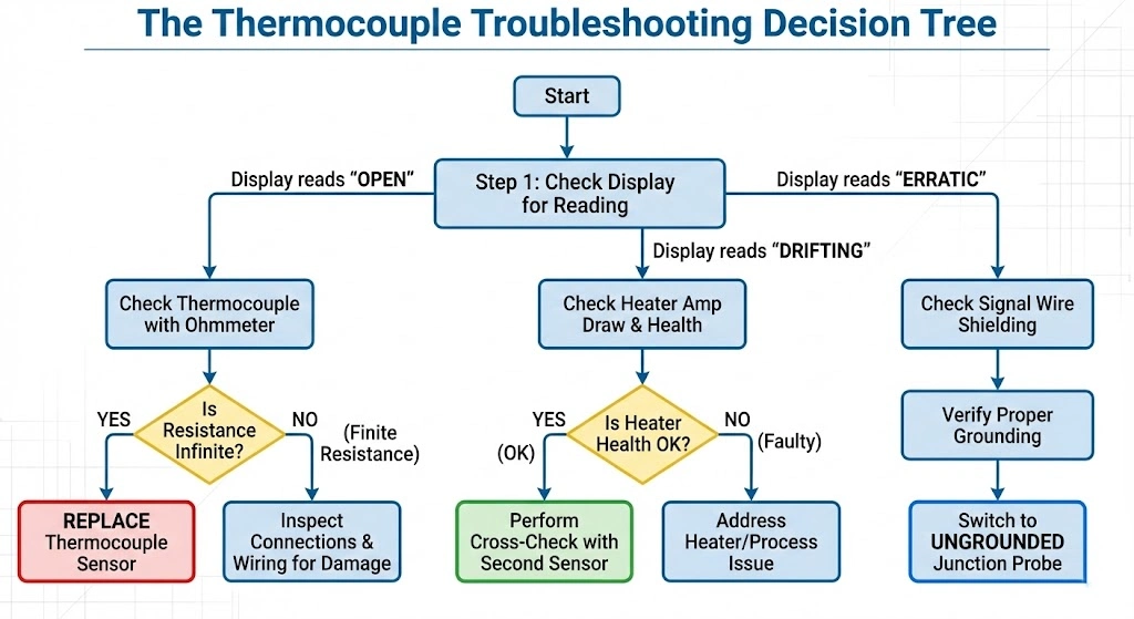
This article is your Field Engineer’s Survival Kit. We will bypass the academic theory and provide a “Battle-Tested” diagnostic framework. We classify failures into three distinct categories:
The Dead (Open Circuit)
The Liar (Drift)
The Crazy (Erratic/Noisy)
By the end of this guide, you will be able to isolate the fault using nothing but a standard multimeter in under 15 minutes.
Before you tear apart the conduit, perform this 60-second health check. This is the first step in any triage process.
Tools Needed: A standard Digital Multimeter (DMM).
Test A: The Continuity Test
Power Down: Turn off the control loop to prevent false alarms.
Disconnect: Remove the thermocouple wires from the controller or transmitter terminals. Do not measure while connected; the controller’s internal circuitry will give you a false reading.
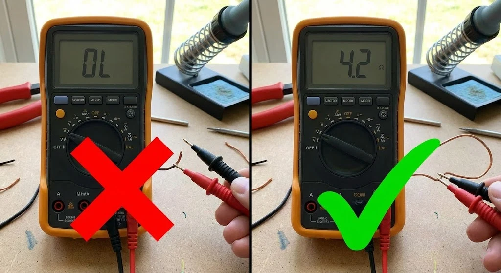
Measure Ohms ($\Omega$): Place your multimeter probes across the two thermocouple leads (e.g., Red and Yellow).
Resistance Reading
Diagnosis
Action
< 10 $\Omega$
PASS. The junction is intact.
Sensor is likely good. Check Controller/Wiring.
Infinite (OL)
FAIL. Open Circuit.
Broken junction or wire. Replace Sensor.
> 100 $\Omega$
WARNING. High Resistance.
Wire is thinning/corroded or connection is loose. Replace soon.
Test B: The Ground Insulation Test
Keep the sensor disconnected.
Place one probe on a lead wire and the other probe on the outer metal sheath of the probe.
Result: It should read Infinite (OL) (unless you are specifically using a Grounded Junction probe).
Diagnosis: If you see continuity (low Ohms) on an Ungrounded probe, the insulation has failed. You have a “Short to Ground,” which invites ground loops and noise.
How to test a thermocouple with a multimeter for open circuit.
Failure Mode A: “Open Circuit” (The Sensor is Dead)
This is the most common failure. The circuit is broken, and the electrons cannot flow. The controller sees infinite impedance and triggers the “Burnout” alarm.
Thermal Fatigue & Cycling
If your process involves rapid heating and cooling (e.g., a batch annealing furnace), the metal wires inside the probe expand and contract at different rates than the sheath.
The Physics: Over thousands of cycles, this mechanical stress acts like bending a paperclip back and forth. Eventually, the wire snaps, usually near the hot junction.
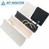
The Solution: Upgrade to Mineral Insulated (MI) Cable. MI cable packs the wires in highly compressed Magnesium Oxide (MgO) powder, which acts as a shock absorber and supports the wires against mechanical stress.
The “Connector” Trap
Before you throw away the sensor, check the back of the plug.
The Issue: In high-vibration environments, the screw terminals inside the standard thermocouple plug often back out.
The Fix: Open the plug. Tighten the screws. Check for white powder (oxidation) on the terminals, which acts as an insulator.
Failure Mode B: “Drift” (The Sensor is Lying)
Drift is the most dangerous failure mode because it is silent. The controller thinks the temperature is 900°C, so it keeps heating. But the actual temperature is 950°C. You don’t find out until your Quality Control lab rejects the batch for being “over-cooked.”
Why Thermocouples Drift
Thermocouples do not drift because of “age”; they drift because of chemical contamination.
Decalibration: At high temperatures, the alloy elements vaporize or diffuse. For example, in Type K thermocouples, the Chromium can oxidize (Green Rot), leaving behind a wire that is chemically different from the original standard.
The Consequence: A different chemical composition generates a different voltage for the same temperature.
The “In-Situ” Test Method (Do Not Remove!)
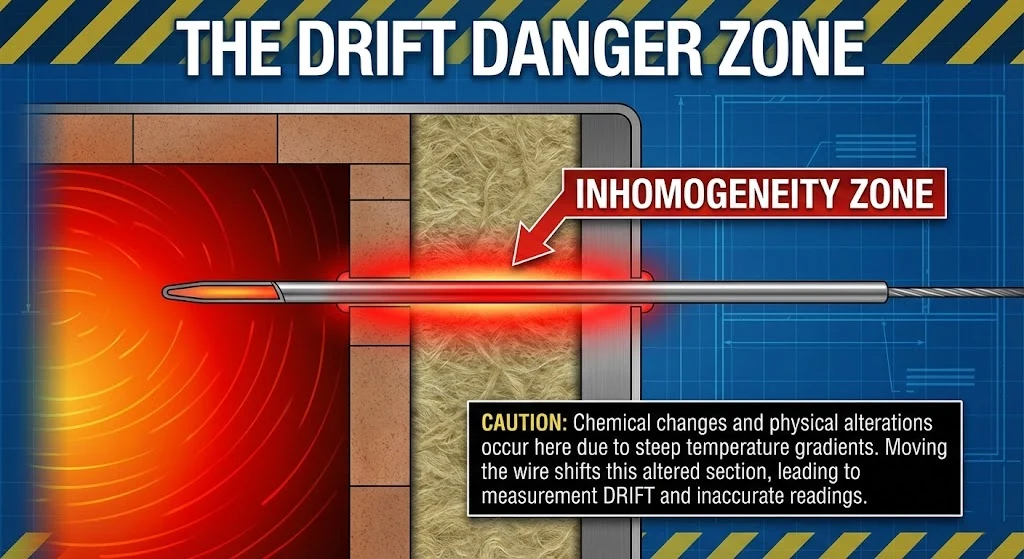
Critical Warning: Do not remove an old thermocouple to calibrate it in a lab furnace.
Why? The chemical damage is often localized to a specific section of the wire (the temperature gradient zone). If you move the sensor to a calibration oven, that damaged section might be at a different depth, creating a “false pass” result.
The Correct SOP: Perform a Cross-Check. Insert a brand new, calibrated “Reference Probe” into the measurement port right next to the suspect probe. Compare the readings while the process is running. If they deviate by >1%, replace the old sensor.
Thermocouple inhomogeneity and drift explanation diagram.
Failure Mode C: “Erratic Readings” (The Sensor is Crazy)
If your temperature reading is jumping wildly (e.g., 200°C -> 205°C -> 190°C -> 210°C) within seconds, physics says this is impossible. Large masses of steel do not cool down and heat up that fast. The sensor is picking up Electrical Noise.
Electrical Noise (EMI/RFI)
Thermocouples generate a tiny signal (millivolts). A 5V power cable running nearby is like a megaphone shouting next to a whisper.
The Culprit: Variable Frequency Drives (VFDs), large motors, and arc welders are massive sources of Electromagnetic Interference (EMI).
The Fix: Never run thermocouple extension wire in the same conduit as high-voltage power lines. Maintain at least 12 inches of separation.
Solving Ground Loops
This is the nemesis of instrumentation technicians.
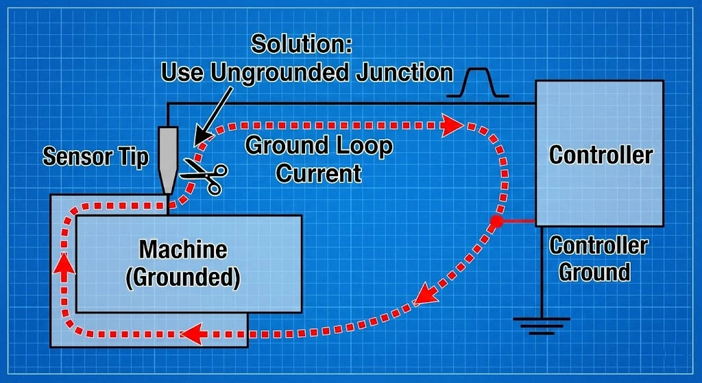
The Scenario: The tip of the thermocouple touches the machine chassis (Earth Ground A). The controller is grounded at the panel (Earth Ground B).
The Physics: Ground A and Ground B are rarely at the exact same potential. This voltage difference causes a “loop current” to flow through your thermocouple wire. This extra current distorts the millivolt signal.
Actionable Fix Checklist:
Switch to Ungrounded Junctions: The sensing element floats in MgO powder and never touches the sheath.
Use Twisted Shielded Pair Wire: The twisting cancels out magnetic noise.
The Golden Rule of Shielding: Connect the drain wire (shield) to ground at ONE END ONLY (preferably the signal source/panel end). If you ground both ends, you create an antenna for noise.
Ground loop interference diagram in thermocouple circuits.
Preventative Maintenance Checklist
Stop fighting fires and start preventing them. Add this to your PM (Preventative Maintenance) schedule.
Monthly: Open the connection head/box. Check that terminal screws are tight. Vibration loosens them over time.
Quarterly: Perform an “In-Situ” comparison calibration for critical control loops.
Annually: Proactive replacement. If a sensor runs continuously above 1000°C, do not wait for it to fail. The metallurgical structure is already compromised. Replace it during the annual shutdown.
Visual Inspection: Look for “pitting” or black corrosion on the metal sheath. This indicates chemical attack. If the sheath is compromised, the sensor is next.
How do you check if a thermocouple is working with a multimeter?
et your digital multimeter to measure Resistance (Ohms/$\Omega$). Disconnect the sensor from the controller. Measure across the two lead wires. A functional thermocouple should read very low resistance (typically 1-10 Ohms). If the meter reads “OL” (Infinite), the internal junction is broken (Open Circuit).
What causes thermocouple readings to jump around?
Erratic or “jumping” readings are usually caused by electrical noise (EMI) from nearby motors, VFDs, or high-voltage cables. It can also be caused by a loose wire connection or a “ground loop,” where the sensor signal is being corrupted by current flowing through the machine ground.
How often should thermocouples be replaced?
It depends on the operating temperature. For critical applications running >1000°C, we recommend proactive replacement every 6-12 months to avoid drift. For low-temperature applications (<400°C), thermocouples can last for many years until they mechanically fail.
Can a thermocouple fail high?
Thermocouples usually fail “Open” (infinite). However, a “short circuit” in the extension wire before the tip will create a secondary junction. The controller will read the temperature at that short (e.g., room temperature) instead of the process temperature. If the controller tries to compensate by heating up, the actual process temperature will go extremely high, even though the reading is low.