You have tuned your PID loop perfectly. Your integral and derivative terms are calculated to the decimal point. Yet, your process temperature is still oscillating like a heartbeat, and your heater contactors are chattering themselves to death.
The problem likely isn’t your controller settings. It is a fundamental conflict in physics occurring at the tip of your sensor.
In industrial process control, engineers often default to buying the sensor with the “fastest response time,” assuming speed equals accuracy. This is a fallacy. In modern factories filled with Variable Frequency Drives (VFDs) and high-voltage motors, “speed” often comes with a penalty: Electrical Noise.
This guide explores the three main thermocouple junction types—Grounded, Ungrounded, and Exposed. We will move beyond the catalog descriptions and analyze the physics of heat transfer vs. electrical isolation, helping you solve the “Speed vs. Stability” equation for your specific application.
Before we dive into the thermal dynamics, let’s define the physical construction of the sensor tip.
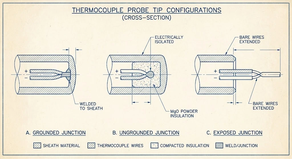
Grounded Junction (The Sprinter): The thermocouple wires are physically welded directly to the inside of the metal probe tip. The sheath and the wires are one electrical mass.
Ungrounded Junction (The Hazmat Suit): The thermocouple wires are suspended in compacted Magnesium Oxide (MgO) powder. They are electrically isolated from the metal sheath.
Exposed Junction (The F1 Car): The wires extend beyond the sheath, exposing the naked bead directly to the environment.
Cross section diagram of grounded ungrounded and exposed thermocouple junctions.
Deep Dive: Grounded Junctions (Speed Demon)
The Grounded junction is the most common default configuration for general-purpose applications, but it carries a hidden risk.
The Physics of Heat Transfer
Why is it so fast? It comes down to Thermal Resistance (R{th}).
Heat travels from the process medium $\rightarrow$ Metal Sheath $\rightarrow$ Weld Point $\rightarrow$ Sensor Wire.
Because the wire is part of the sheath, there is zero thermal barrier between the protection tube and the sensor. The heat transfer is conductive and immediate.
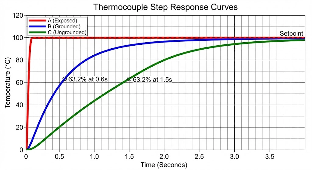
Data Point: In water flowing at 1 m/s, a standard 6mm (1/4 inch) grounded probe reaches 63.2% of its final reading (1 Time Constant) in approximately 0.6 seconds.
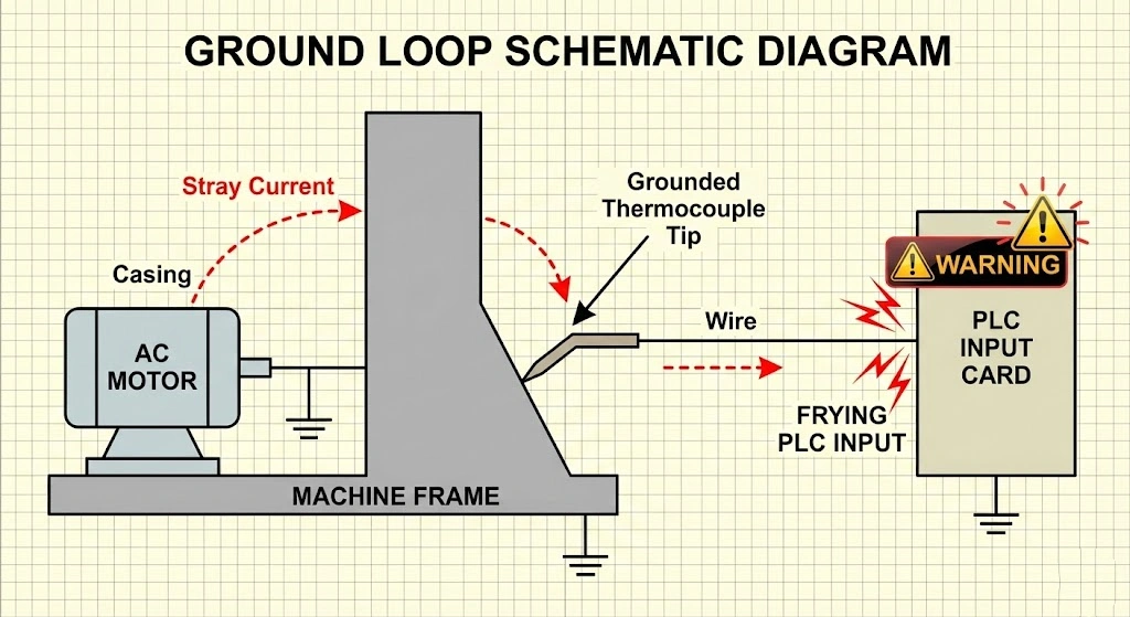
The Hidden Danger: Ground Loops
The strength of the grounded junction is also its Achilles’ heel. Because the wire is welded to the sheath, the sensor wire is electrically connected to the machine it is screwed into.
The Scenario: You install a grounded thermocouple into the frame of a large injection molding extruder. The machine frame has a floating voltage potential of 2V due to a small leak from a motor winding. Your PLC controller is grounded to a clean panel ground (0V).
The Result: A Ground Loop. Current flows from the machine, through the thermocouple tip, up the wire, and into your delicate PLC input card. This creates offset errors, erratic jumping readings, and can eventually burn out the input channel.
Best Use Case:
High-pressure static liquids (hydraulic oil).
Systems with zero electrical noise.
Applications requiring rapid response to catch “thermal runaway” events.
Deep Dive: Ungrounded Junctions (The Shielded Guardian)
If you are working in a modern automated factory, the Ungrounded (Insulated) junction is usually the superior engineering choice.
Electrical Isolation is Key
In an ungrounded junction, the thermocouple bead is surrounded by Magnesium Oxide (MgO) insulation. This powder has high dielectric strength.
The Benefit: It breaks the galvanic path between the process and the controller. Even if your machine frame is “hot” with stray voltage, the sensor signal remains floating and clean.
VFD Environments: In plants with heavy VFD usage, electromagnetic interference (EMI) is rampant. An ungrounded junction, combined with a twisted-shielded extension wire, provides the highest Signal-to-Noise Ratio (SNR).
The “Lag” Factor
You must pay for this protection with time. Heat must now travel:
Process → Metal Sheath → MgO Powder (Insulator) → Sensor Wire.
MgO is a great electrical insulator, but it is a mediocre thermal conductor compared to metal.
Data Comparison: That same 6mm probe, now ungrounded, will have a response time of 1.5 to 2.5 seconds.
The Engineering Question: Does your massive heat treatment furnace really change temperature faster than 2 seconds? Likely not. In 95% of large thermal mass applications, this lag is irrelevant, but the noise protection is vital.
Deep Dive: Exposed Junctions (Air & Gas Only)
This is a specialized tool for a specific medium: Gas.
Zero Thermal Mass
An exposed junction removes the sheath entirely. The “Time Constant” is determined solely by the mass of the wire bead and the convective heat transfer coefficient of the air.
Response Time: Can be as fast as 0.05 to 0.1 seconds depending on wire gauge.
Application: Measuring air temperature in HVAC ducts or analyzing the profile of a gas burner flame.
The Fragility Limit
Strict Warning: Never use exposed junctions in liquids or high-pressure environments.
Moisture: Will cause immediate corrosion and drift.
Pressure: The seal is weak; high pressure will force gas up the transition tube.
Contamination: The wire is naked. Any particulate matter will adhere to the junction and alter the calibration.
Technical Comparison Matrix
Use this decision matrix to select the right junction for your Bill of Materials (BOM).
Attribute
Grounded
Ungrounded
Exposed
Response Time
Fast (~0.6s)
Medium (~1.5s)
Instant (<0.1s)
Ground Loop Risk
High (Direct Path)
None (Isolated)
N/A (Insulated Mount)
Electrical Noise Immunity
Low
High
Low
Pressure Rating
High (Solid Sheath)
High (Solid Sheath)
Low/None
Mechanical Strength
Excellent
Excellent
Poor (Fragile)
Typical Application
Injection Molding, Static Tanks
VFD Drives, PID Loops, Furnaces
Air Ducts, Gas Analysis
Thermocouple response time graph comparing grounded vs ungrounded vs exposed junctions.
How to Calculate “Time Constant” (τ)
To truly master sensor selection, you must understand the math behind “Speed.” We define speed using the Time Constant ($\tau$). One time constant is the time required for the sensor to reach 63.2% of a step change in temperature. It takes 5 time constants ($5\tau$) to reach 99% of the reading.
The Formula:
τ=Vc/hA
Where:
= Density of the sensor mass
V = Volume of the sensor sensing tip
c = Specific heat capacity
h = Convective heat transfer coefficient
A = Surface area available for heat transfer
The Engineer’s Takeaway:
Look at the variables. To decrease $\tau$ (make it faster), you can either increase τ (stir the fluid) or decrease V (Volume).
Pro Tip: If you absolutely need the electrical isolation of an Ungrounded sensor but the response time of a Grounded sensor, do not compromise on the isolation. Instead, reduce the probe diameter.
Switching from a 6mm (1/4″) Ungrounded probe to a 3mm (1/8″) Ungrounded probe cuts the volume significantly, bringing the response time back down to near-grounded levels while keeping your PLC safe from noise.
Which is better: grounded or ungrounded thermocouple?
It depends on the application. Grounded is better for static, non-electrical applications (like heating a tank of oil) where fast response is critical. Ungrounded is better for industrial electronics (PLC/VFD control) to prevent electrical noise and ground loops. For 90% of modern industrial automation, Ungrounded is the safer choice.
Does an ungrounded thermocouple affect accuracy?
No. The junction style does not affect the final steady-state accuracy of the temperature reading. It only affects the response time (how long it takes to reach that temperature). A Type K ungrounded probe and a Type K grounded probe will eventually read the exact same temperature; the ungrounded one just takes a second longer to get there.
How do I tell if my thermocouple is grounded or ungrounded?
You can test this in 10 seconds with a multimeter. Set the meter to “Continuity” (Beep) or Resistance ($\Omega$). Place one probe on one of the lead wires (pin) and the other probe on the metal sheath of the sensor. -Beep / Low Ohms: It is Grounded. -No Beep / Infinite (OL): It is Ungrounded.
Can I use a grounded thermocouple with a VFD?
It is not recommended. Variable Frequency Drives (VFDs) generate significant high-frequency electrical noise that travels through the machine ground. A grounded thermocouple acts as an antenna, picking up this noise and sending it directly to your controller. This results in erratic, jumping temperature readings. Always use Ungrounded thermocouples with VFDs.